
User manual


Installation and Setup
2-8 ProMaster 2500 User Manual
Installing and
Removing Chucks
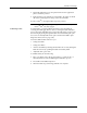
Three chucks are provided with the system. Each chuck has a different
tip diameter that corresponds to the size and dimensions of different
devices. Figure 2-7 shows the appropriate chuck for each supported
package type.
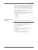
CAUTION: Chucks are released from the beam suddenly. When changing
a chuck, do not position the beam over the label application
area, the SPA pins, or programming module. The sudden
release of the chuck from the beam may damage those
components. Usecaretopositionthebeamonlyinthe area
described below before attempting to remove chucks.
Change the chuck with the beam directly over one of the two main plate
device recesses. Keep the beam raised by holding it up with two fingers
while you use a downward pulling/twisting motion to remove the
chuck. With one hand on the beam for support, insert the new chuck by
lifting it straight up until it snaps into position.
Figure 2-7
Chuck Selection Chart
DEVICE
TYPE
PLCC
DIP
LMN
20-PIN
28-PIN
32-PIN
44-PIN
52-PIN
68-PIN
84-PIN
300 mil
600 mil
1850-3
Recommended
Alternate
SOIC 150 mil
220 mil
300 mil
330 mil
420 mil
500 mil
K
CHUCK
ProMaster 2500