
User manual


Computer Remote Control
E-22 ProMaster 2500 User Manual
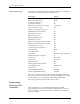
CRC Error Codes
Following is a list of error codes that appear while the 2500 programming
electronics are being operated in the computer remote control mode.
These error codes will be returned by the 2500 programming electronics
after they receive the
X
command. Normally, you should send the
X
command after the 2500 programming electronics send an
F
in response to
a command. The list is in numerical order, according to the error code.
1F Cannot erase device error
20 Non-blank device
21 Illegal bit error
22 Device programming error
Note: The two following errors have the same error code. For either error to
appear, you must have selected command
n23]
(Select Verify Option). If
1
was specified as the variable, use the first description. If
2
was specified,
use the second description.
23 Verify data error (Vcc Nominal)
23 Verify data error (Vcc low)
24 Verify data error (Vcc high)
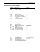
59] Enable/disable capacitor
configuration test >
5A] Display list of parameters See Application Note*
5B] Clear vector data >
5C] Load system files for CM algorithm
disk >
5D] Write system files to CM disk >
5E] Write algorithms to CM disk >
n
5F] Select algorithm source drive for
creating CM algorithms >
60] Get number of sectors dd>
n
61] Get sector configuration settings HHHH HHHH>
nhhh...hhhh
62] Set sector configuration settings >
xxx...xxxx
64] Select device part number for CM (use
xxx...xxxx
33] to select manufacturer) >
A7] Swap bytes >
DC] Device check See Application Note*
EB] Input JEDEC data from host >
EC] Output JEDEC data to host >
FC] Restore CRC entry default parameters >
FD] Restore user-defined CRC parameters >
FE] Save user-defined CRC parameters >
* This Application Note, “UniSystem Computer Remote Control,” is available from Data I/O
Customer Support.
Command Description Response