
User manual


Introduction
1-10 3/97 ProMaster 2500 User Manual
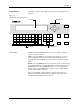
Beam
—With a chuck on the beam head, a pick-and-place method is used
to gently transport devices. Information in the Task instructs the beam to
rotate the device so that programming and labeling are performed with
the correct device orientation. The beam’s position is automatically
calibrated each time the system is initialized.
Chuck
—Located on the end of the beam, the chuck achieves an air-tight
seal on the device so the beam’s vacuum can pick up and release devices
as they are processed.
Programming Station
—Opening in the main plate through which the
SPA pins can be seen. This is where the programming module is installed
and devices are programmed.
Programming Module
—Installed over the SPA pins of the 2500, serves
as the socket for the device during the programming operation. Devices
are inserted by the beam into a DIP, PLCC, or SOIC programming
module, where they are programmed or tested by the system.
Internal Features
The internal features include all the component parts located beneath the
main plate, in the 2500’s base. These include the system’s power supplies,
firmware and controller board, motors, programming electronics, and
other components.
WARNING:Raising the main plate with power on will expose you to
harmful, high voltage. Only trained service technicians
should perform the diagnostic tests that require lifting the
main plate while the power is on.