
User manual


Repair and Replacement Procedures
7-36 ProMaster 2500 User Manual
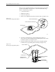
The pin insulation block is symmetrical so no specific polarity
orientation is required; it may be inserted into the programming
block either way.
6. Carefully plug the programming block onto the circuit board using
the block’s alignment pins as guides.
The programming block is symmetrical so no specific polarity
orientation is required; the block may be inserted on the circuit board
either way. The block is seated on the board correctly when rests
against the board on all sides without a gap. If a gap exists, remove
and reseat the block.
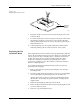
7. Turn the module upside down and reinsert the two Phillips screws
on the bottom of the circuit board.
8. Reinsert the spring-loaded module pins in the insulation block.
Note: One end of the module’s gold contact pin is spring-loaded and telescopes
when pressed. Reinsert the module pin into the new insulation block with
the telescoping end up so that end contacts the device lead during
programming.
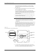
Most SOIC programming modules ship without some pins in the pin
insulation block at the narrow end of the module board. Start
reinserting pins in the block holes nearest the wide end of the circuit
board and work toward the narrow end. Fill both insulation blocks
with an equal number of module contact pins. Figure 7-27 shows a
device over the pins at the wide end of the board.
9. To ensure that the contact pin is seated correctly, use the pliers to
press down on each pin until it is flush with the module’s top surface.
Do not use any object to push the pin farther down the hole.
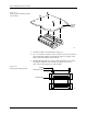
Figure 7-27
Pin Insulation Block in the Programming Module
2280-2
PIN INSULATION
BLOCK
PROGRAMMING
BLOCK
CIRCUIT BOARD
FRONT
OF
HANDLER
DEVICE