
User manual


Repair and Replacement Procedures
ProMaster 2500 User Manual 7-35
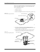
2. Using the needle nose pliers, insert the replacement pin in the same
hole in the block.
3. To ensure that the pin is seated correctly, use the pliers (or flat end of
a flat-blade screwdriver) to press down on the spring-loaded pin
until it is flush with the block. Do not use any object to push the pin
farther down the hole.
4. Continue replacing any other questionable pins, and then test the
module by running a device-related operation on the system.
Replacing the Pin
Insulation Block
After a high number of device insertions in the programming module, the
holes in the pin insulation block may become enlarged or elongated. This
increase in hole size may eventually allow too much movement of the
module pins while a device is being inserted, resulting in a higher
number of continuity test and device programming errors. If you
experience a gradual increase in these failures, examine the insulation
block for enlarged pin holes.
If you determine that the pin insulation block needs to be replaced,
perform the following steps.
1. Remove all module pins (gold spring-loaded pins) from both pin
insulating blocks.
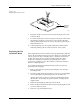
2. Turn the module upside-down and remove the two recessed Phillips
screws that hold the programming block to the circuit board.
After the screws have been removed, the programming block will
still be held to the board by the physical tension caused by the two
alignment pins.
3. Pull the board straight up and away from the block.
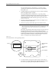
4. Remove both pin insulation blocks from the programming block with
a pair of needle-nose pliers.
5. Insert two new pin insulation blocks.
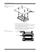
Figure 7-26
Replacing the Defective Pins
1930-1
PRINTED
CIRCUIT
BOARD