
User manual


Repair and Replacement Procedures
7-34 ProMaster 2500 User Manual
9. When the contact set is in position, insert and tighten the two hex
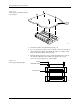
screws that hold it in place.The programming block consists of two
pieces: a top and a base. The contact set screws hold the top and base
together.
Keep at least one contact set installed so the top does not separate
from the base. If the top and base come apart, refer to page 7-38, step
9 for instructions on reassembling the programming block.
10. Replace the worn contact sets on the remaining three sides.
Note: Replace all four contact sets. Mixing new sets with old will make it
difficult to determine which of the sets is causing a problem.
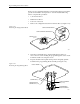
11. Turn the assembled programming block upside-down and insert the
device ejector pin and its spring into the programming block.
CAUTION: The capacitor configuration blocks should not be installed
on the board when the programming block is being inserted
on the programming module board. Pins on one of the
contact sets might hook on the block and become bent or
damaged.
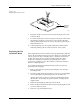
12. Using the block alignment pins as guides, carefully slide the board
and block together.
13. Install the two hex screws mounting the block to the board.
14. Install the configuration blocks for the next device to be
programmed.Refer to page 4-7 for more information on configuring
the module.
15. Check the operation of the programming module using a device type
that usually gives you high yields.
Replacing Pins on a
SOIC Programming
Module
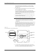
Use the following procedure to replace the spring-loaded pins on any of
the SOIC programming modules.
CAUTION: To avoid possible damage to the system components, this
procedure should be performed only by a qualified service
technician.
1. Set the module on a flat surface and grasp the defective pin with a
pair of needle nose pliers. Pull the pin straight up and out of the
programming block (see Figure 7-26).