
User manual


Repair and Replacement Procedures
ProMaster 2500 User Manual 7-33
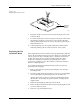
4. The device ejector pin and ejector spring are loose and will drop out
into your hand when you turn the block upright (see Figure 7-24). Set
these aside; you will reinstall them later.
5. Use a 1/16-inch hex driver to remove the two screws holding the
contact set in place.
6. Gently pivot the base of the contact set out from the programming
block and then lift the set straight up (see Figure 7-25).
7. Wipe the new contacts with a DeoxIT pen from the top of each
contact lead to its end (the portion of the contact that touches the
device’s leads). Remove any excess DeoxIT with a clean, dry cotton
swab. Preparing the leads in this way ensures that they are clean and
well lubricated.
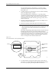
8. Insert the new contact set into the programming block. Hold the set
at an angle and gently feed the tips of the contact set into the holes in
the top of the programming block.
Make certain that all the tips in the set have seated into their holes
before swinging the set’s base into position along the block. Failure to
insert all the tips in their correct positions could result in damage to
the contacts.
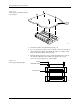
Figure 7-24
Removing the Device Ejector Pin
and Spring
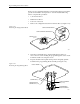
Figure 7-25
Removing the Contact Set
1681-2
DEVICE EJECTOR PIN
DEVICE EJECTOR SPRING
PROGRAMMING
BLOCK ASSEMBLY
GOLD PIN
1668-1
CONTACT SET
PROGRAMMING BLOCK
ASSEMBLY
SCREW (1 of 2
per Contact Set)