
User manual


Repair and Replacement Procedures
7-32 ProMaster 2500 User Manual
When you have determined that the contacts need replacing, perform the
operations described in the steps below. You will need the following
items to complete this procedure:
• 1/16-inch hex driver
• 0.050-inch hex driver
• Four new contact sets
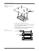
1. Remove the configuration blocks from all four sides (see Figure 7-22).
2. Turn the board upside down. Use the 0.050-inch hex driver to
remove the two screws holding the programming block to the circuit
board. Be careful not to strip the screws.
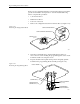
3. Keep the module in the upside-down position and gently pull the
board from the programming block assembly (see Figure 7-23).
Figure 7-22
Removing the Configuration Blocks
Figure 7-23
Removing the Programming Block
1649-1
CONFIGURATION BLOCK
CONFIGURATION CONNECTOR
CONTACT SET
(1 of 4)
20A
1X
4X
BLOCK ALIGNMENT
PIN (1 of 2)
PROGRAMMING
BLOCK ASSEMBLY
CIRCUIT BOARD
SCREW HOLE (1 of 2)
CONFIGURATION
CONNECTOR (1 of 4)
1669-2