
User manual


Repair and Replacement Procedures
ProMaster 2500 User Manual 7-31
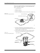
6. Gently feed the new contact set through the underside of the module
into its operating position. The contact set has a notch that fits the
ridge in the module to set the correct alignment. Confirm that these
two are seated before proceeding.
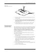
7. Set the retaining bar in position on the contact set, and use the two
screws to hold the bar in place.
8. Insert the contact set on the other side, and tighten its retaining
screws.
9. Reinstall the programming module on the circuit board, observing
the correct orientation as you noted in the first step.
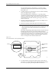
Replacing Contacts
on a PLCC Module
When contacts fail because of a high number of insertions, they generally
exhibit a gradual, progressive increase in programming failures over
several days or weeks. Sudden onset of a high programming failure rate
is usually an indication of some other problem and not a sign of worn
contacts.
One method of keeping track of the number of devices programmed is to
use TaskLink’s Session Data Logging feature (see page 3-19). When
enabled, this option maintains a log of all TaskLink operations and
continuously updates the statistics in a file on your PC. One of the
categories recorded is a count of the number of devices processed during
each Task run. These statistics allow you to calculate the number of
insertions for each device type.
CAUTION: To avoid possible damage to the system components, this
procedure should be performed only by a qualified service
technician.
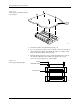
Figure 7-21
Removing or installing the Contact Set
1929-1
CONTACT SET
RETAINING BLOCK (1 of 2)
SCREW (2 per side)
VIEW FROM BELOW
CROSS SECTION
CROSS SECTION PLANE
TILT CONTACT SET BEFORE
REMOVING OR INSERTING