
User manual


Repair and Replacement Procedures
7-30 ProMaster 2500 User Manual
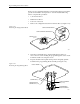
3. Turn the module so the underside is facing you.
4. Use a 1/16-inch hex wrench to remove the two screws (on the sides of
the module) that hold the retaining block in place (see Figure 7-20).
Remove the retaining bar and set it aside.
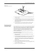
5. Hold the black plastic base of the contact and gently remove the set
through the underside of the module (see Figure 7-21). Do not
remove the set through the top of the module.
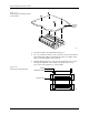
Figure 7-19
Removing the DIP Module from the
Circuit Board
Figure 7-20
Removing the Retaining Block
1927-1
PRINTED
CIRCUIT
BOARD
1928-1
SCREW
RETAINING BLOCK
CONTACT SET