
User manual


Repair and Replacement Procedures
ProMaster 2500 User Manual 7-29
Keyboard/Display Assembly Replacement
This procedure describes the steps required to remove and replace the
keyboard/display assembly.
Replacing the
Keyboard/Display
Assembly
If the keyboard/display assembly fails, follow the steps below to replace
it.
1. Turn off the 2500 and remove the power cord.
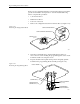
2. Use the flat edge of a flat-head screwdriver (or a table knife) to pry up
the bottom left and top sides of the keyboard/display assembly,
which is affixed with two-sided tape.
CAUTION: Do not pry up the right side of the display.
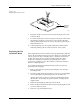
3. Pull the keyboard/display assembly away from the 2500.
Note: The keyboard/display assembly is held in place with double-sided tape.
4. Remove the two cables that connect the keyboard/display assembly
to the controller board.
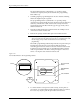
5. Apply double-sided tape to the underside of the new keyboard/
display assembly.
6. Connect the two controller board cables to the new keyboard/display
assembly.
7. Press the new keyboard/display assembly into place.
Programming Module Components Replacement
These procedures describe the steps required to replace failed
components on programming modules.
Replacing Contacts
on a DIP Module
Use the following procedure to replace the contact sets on a
programming module. Replace both sides at the same time.
1. Mark the module on the end next to the narrower end of the circuit
board. You must reinstall the module on the board in the correct
orientation. It is possible to reinstall the module backwards on the
board.
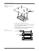
2. Remove the four hex screws from the underside of the programming
module board and remove the printed circuit board (see Figure 7-19).