
User manual


Repair and Replacement Procedures
ProMaster 2500 User Manual 7-27
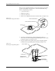
10. Use a 6/64-inch hex wrench to remove the two screws that hold the
air cylinder pin in place.
11. Hold the beam in place while you use a 3/32-inch hex wrench to
gently push the air cylinder pin through the beam.
12. Gently lift the beam up and away from the beam shafts.
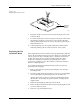
13. Remove the two 1/16-inch set screws in the beam motor drive pulley.
14. Disconnect the beam motor cable.
15. Remove the single 3/32-inch hex mounting screw in the beam head
pulley.
16. Pull up the beam head pulley and remove the beam rotation belt.
17. Remove the motor drive pulley.
18. Use a 1/16-inch hex wrench to remove the four motor mounting
screws, then remove the beam head rotation motor.
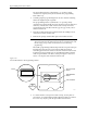
19. Use a 3/32-inch hex wrench to remove the two air quick connects
(insert the hex wrench into the quick connect openings).
20. Use a 3/32-inch hex wrench to remove 20 screws in the baffle plate.
21. Use a 1/4-inch hex wrench to remove the three remaining pan head
screws in the baffle plate.
22. Peel off the old air channel gasket.
23. Place the new air channel gasket onto the baffle plate.
Note: Make sure the air channel gasket does not block any air and vacuum holes.
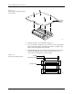
Figure 7-17
Beam Cable and Switch Locations
2287-1
VACUUM SENSOR CABLE
CABLE HARNESS GUIDE
BEAM TRAVERSE
MOUNTING BLOCK
RIGHT END PLATE
LIMIT BAR
BEARING COVER PLATE
REAR CARRIAGE SHAFT
FRONT COVER SHAFT
VACUUM SENSOR
SWITCH
AIR CYLINDER
PIN SCREW
(1 on each side)