
User manual


Repair and Replacement Procedures
ProMaster 2500 User Manual 7-17
11. Carefully pull the input orbital assembly off the motor spindle and
then slide the assembly to the left, until the right side of the assembly
is free.
12. Install the repaired input orbital assembly and re-assemble all of the
disconnected cables and components.
Replacing the
Output Orbital Tube
Clamp
If an orbital tube clamp on the output orbital tube clamp assembly needs
to be repaired, follow the steps below to remove and reinstall it.
1. Turn off the 2500 and remove the power cord.
2. Remove the PE assembly, as described on page 7-3.
3. Lift the main plate and locate the round input orbital motor clamp.
Loosen the set screw and remove the motor clamp.
4. Remove the two 3/32-inch hex screws that hold the right orbital
alignment block to the underside of the main plate. Slide the right
orbital retaining block off the dowel pin and let the block dangle from
the cables.
5. Remove the two 3/32-inch hex screws that hold the left orbital
alignment block to the underside of the main plate. Remove the left
orbital alignment block.
6. Remove the 3/32-inch hex screw that holds the grounding strap to
the underside of the main plate.
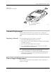
7. Use a needle nose pliers to remove the track springs.
8. Remove the four 3/32-inch hex screws on the underside of the output
orbital plate.
9. Cut the tie wraps and disconnect the four optic cable connectors and
the single microswitch cable connector.
10. Carefully pull the output orbital assembly off the motor spindle.
11. Install the repaired output orbital assembly and re-assemble all of the
disconnected cables and components.
Figure 7-14
Remove the Track Springs
2309-1
OUTPUT ORBITAL
ASSEMBLY
SPRING (1 of 4)
CENTER POST (1 of 2)