
User manual


Repair and Replacement Procedures
7-16 ProMaster 2500 User Manual
Mechanical Assembly Removal
Replacing the Input
Orbital Tube Clamp
If the tube clamp on the input orbital tube clamp assembly is too loose,
does not close, or produces too much tension, follow the steps below to
replace it.
1. Turn off the 2500 and remove the power cord.
2. Remove the PE assembly, as described on page 7-3.
3. Lift the main plate and locate the round input orbital motor collar on
the cam spindle. Loosen the set screw and remove the motor collar.
4. Remove the two 3/32-inch hex screws that hold the rear orbital
alignment block to the underside of the main plate. Slide the rear
orbital retaining block off the dowel pin and let the block dangle from
the cables.
5. From above the main plate, remove the two 3/32-inch hex screws
that hold the front orbital alignment block to the main plate. Remove
the front orbital retaining block from the underside of the main plate.
6. Support the left side of the orbital assembly while you remove the
7/64-inch hex retaining screw on the right side of the orbital
assembly.
7. Remove the 3/32-inch hex screw that holds the grounding strap to
the underside of the main plate.
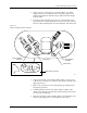
8. Use a needle-nose pliers to remove the track springs.
9. Remove the four 3/32-inch hex screws on the underside of the input
orbital plate.
10. Cut the tie wraps and disconnect the two optic cable connectors and
the single microswitch cable connector.
Figure 7-13
Remove the Track Springs
2308-1
INPUT ORBITAL
ASSEMBLY
SPRING (1 of 2)
CENTER POST