
User manual


Repair and Replacement Procedures
7-14 ProMaster 2500 User Manual
Replacing the
Thermal Print Head
The thermal print head is mounted on a small printed circuit board
(PCB). Do not attempt to remove the print head from the PCB. The new
print head is mounted on a new board, which should be installed as one
assembly.
1. Turn off the 2500 and remove the power cord.
2. Use a 3/32-inch hex wrench to remove the hex screw that holds the
print head to the print head mounting block.
Note: In the older style thermal printer, there are two print head mounting
screws and limited clearance for a full-size hex wrench to reach the inside
print head mounting screw. Use an L-shaped 3/32-inch hex wrench that
has been modified by grinding down the extension end so it is between
1/4-inch and 5/16-inch long. Use a 7/64-inch hex wrench to remove the
hex screw that holds the ribbon cable clamp.
3. Pull out the print head assembly and unplug the ribbon cable (J-27)
from the print head PCB cable connector.
4. Install the new print head assembly.
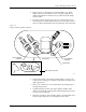
Figure 7-12
Removing the Print Head
2390-1
PRINT HEAD
SCREW (1 of 2)
MOUNTING
BLOCK (1 of 2)