
User manual


Repair and Replacement Procedures
7-12 ProMaster 2500 User Manual
10. Follow the same procedure to remove the left orbital alignment block.
11. Support the assembly with one hand while you remove the two 7/64-
inch hex retaining screws (with the white plastic standoff) on the tube
clamp support braces.
12. Carefully slide the back end of the orbital assembly off the orbital
cam spindle. Be careful that the white bushing between these two is
not lost or damaged.
13. When the assembly is off the spindle, slide the entire assembly
toward the back of the 2500 until it is free from the two front support
braces. Let the assembly dangle from the cables.
14. Remove the orbital cam from the motor shaft. Now you are ready to
remove the output orbital motor.
15. From below the main plate, remove the four 1/16-inch hex screws
that holds the output orbital motor to the main plate.
16. Lower the main plate and remove the output orbital motor.
17. Place the new output orbital motor in position on the main plate.
Make sure the power cable is oriented to the right side of the new
output orbital motor.
18. Guide the motor cable through the hole in the main plate.
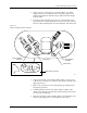
19. Insert the four motor wires into the white plastic Molex connector. Be
sure to insert the wires in the same order (and orientation) as shown
in Figure 7-9.
20. The output orbital motor shaft has a flat edge on one side. Turn the
shaft until the flat edge faces the front of the 2500.
21. The orbital cam has a small hole on its outer edge. Position the cam
on the motor shaft so this small hole is positioned on the right side
(input side) of the shaft.
CAUTION: When you reinstall the orbital assembly, make sure the
white bushing that fits over the spindle stays in position.
22. Reinstall the assembly (in reverse order from the procedure in steps
11-13 above).
23. Reinstall the left and right alignment blocks and the optic block.
24. Rotate the orbital cam to make sure it spins freely and does not rub
against the underside of the main plate. If you feel or hear the cam
rubbing against something, grasp the outer edge of the cam and
gently pull it approximately 3/32 of an inch away from the underside
of the main plate and recheck it again.
25. Install the collar over the cam spindle. The slit in the collar must be
aligned with the slit in the spindle (see Figure 7-10).
26. Turn the orbital cam one final time to check for smooth rotation with
no rubbing.