
User manual


Repair and Replacement Procedures
ProMaster 2500 User Manual 7-9
4. Remove the two 3/32-inch hex screws that hold the rear orbital
alignment block to the underside of the main plate. Slide the rear
orbital alignment block off the dowel pin, and let the block dangle
from the cables.
5. From above the main plate, remove the two 3/32-inch hex screws
that hold the front orbital alignment block to the main plate. Remove
the front orbital retaining block from the underside of the main plate.
6. Support the left side of the orbital assembly while you remove the
7/64-inch hex retaining screw (with the white plastic standoff) on the
right support brace.
7. Remove the 3/32-inch hex screw that holds the grounding strap to
the right support brace.
8. Carefully slide the left side of the input orbital assembly off the
orbital cam spindle. Be careful that the white bushing between these
two is not lost or damaged.
9. When the assembly is off the spindle, slide it to the left until it is free
from the right support brace. Let it dangle from the cables.
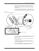
Figure 7-8
Input and Output Orbital Assemblies
2307-1
INPUT ORBITAL
ASSEMBLY
OUTPUT ORBITAL
ASSEMBLY
MAIN PLATE (Underside)
CAM SPINDLE
CAM SPINDLE