
User manual


Repair and Replacement Procedures
ProMaster 2500 User Manual 7-7
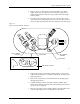
14. Carefully slide the programming electronics assembly away from the
clamp assembly. Figure 7-7 shows the two tracks on the clamp
assembly that fit into grooves on the pin block. The track and grooves
hold the assembly to the underside of the main plate. Do not twist the
programming electronics assembly as you slide it away from the
clamp assembly; doing so may damage the pin block.
15. Set the programming electronics assembly on an antistatic surface.
Figure 7-6
Lower the Clamp Assembly and Remove the Retaining Bar
Figure 7-7
Programming Electronics Assembly Alignment
2070-2
MAIN PLATE
(Underside)
PROGRAMMING
ELECTRONICS
ASSEMBLY
PROGRAMMING MODULE
CLAMP ASSEMBLY
HEX HEAD SCREW
RETAINING BAR
A
J
S
SHIFT
B
K
T
DEL
C
L
U
D
M
V
E
N
W
F
O
X
SHIFT
G
P
Y
H
Q
Z
I
R
ENTER
1
4
7
2
5
8
3
6
9
0
LOW
CASE
RESET
STOP
CAL
START
2066-2
GROOVE
TRACKS
PIN BLOCK
PROGRAMMING
ELECTRONICS
ASSEMBLY
BOTTOM SIDE OF PROGRAMMING
MODULE CLAMP ASSEMBLY