
User manual


Repair and Replacement Procedures
7-6 ProMaster 2500 User Manual
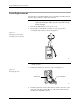
10. Holding the programming electronics from the bottom, remove the
last two screws. Lower the programming module clamp assembly
and let it rest on the black protective shield.
Note: Hold the programming module clamp assembly in place (from below the
main plate) when you remove the assembly from the main plate.
11. Disconnect the two optic cables (S-24 and C-25).
Note: Before removing the air lines as described in the next step, mark the hoses
for proper reinstallation.
12. Remove the two blue and two red air lines from the four quick
connects on the programming module clamp assembly (see Figure
5-2).
13. Remove the retaining bar that holds the PE assembly in place on the
underside of the main plate (see Figure 7-6). Use a 7/64-inch hex
wrench to remove the two hex screws that hold the bar in place. Set
these in a safe place so you can use them to reinstall the PE assembly.
Figure 7-5
Remove the Module Clamp
Assembly Screws
2313-1
SCREW LOCATION (1 of 6)