
User manual


Repair and Replacement Procedures
ProMaster 2500 User Manual 7-5
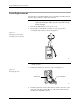
6. Locate the wide ribbon cable that connects the controller/waveform
board with the disk drive. (This is the wider of two ribbon cables
running between the controller/waveform board and the disk drive.)
Mark the polarity of this cable to the connector on the controller/
waveform board so you can reinstall it correctly later. Disconnect this
cable from the connector on the controller/waveform board.
7. Mark the polarity and location of the narrow ribbon cable connecting
the controller/waveform board with the disk drive. Disconnect this
cable from the connector on the controller/waveform board.
8. Locate and label the two RS-232C ribbon cables (terminal and remote
cables) on the controller/waveform board. These are indicated by
two black arrows in Figure 7-4. Mark their connector locations so you
will be able to reinstall them correctly. Disconnect these cables from
their connectors on the controller/waveform board.
9. From above the main plate, locate the six 7/64-inch hex screws that
hold the programming module clamp assembly to the main plate (see
Figure 7-5).
Remove two of the screws holding the back of the assembly and two
of the screws holding the front. Loosen the other two screws, but do
not remove them.
Figure 7-4
Polarity of the Cables on the
Programming Electronics
Assembly
2056-2
DISK
DRIVE
PROGRAMMING
ELECTRONICS
POWER SUPPLY
TO MAIN
CONTROLLER
BOARD
R
R
B
B
R
R
R
(BOTTOM)
(TOP)
B
B
B
BL
R
SYSTEM FAN
CONTROLLER/
WAVEFORM
BOARD
TERMINAL REMOTE
RED AND BLACK
POWER CABLE
TO TERMINAL PORT