
User manual


ProMaster 2500 User Manual 6-1
6
Troubleshooting
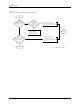
This chapter describes ProMaster 2500 messages and contains
troubleshooting flow charts. Use the flow charts to help determine the
likely cause of problems you may experience while operating the 2500.
Some of the items listed in the flow chart refer to repair and replacement
procedures that should be performed by trained service technicians.
These repair and replacement procedures are described in Chapter 7.
The information in this chapter is presented in the following order:
Messages................................................................................................... 6-1
Troubleshooting Flow Charts................................................................ 6-6
WARNING:Performing the repair and replacement procedures listed
in the troubleshooting flow chart may expose you to
harmful high voltage. To avoid electrical shock or
mechanical injury, only a service technician trained on
electromechanical equipment should perform these
procedures. If you are not a service technician who has
been trained on the 2500, do not raise the main plate.
Messages
This section lists and describes, in alphabetical order, the system error
messages that appear on the 2500’s front panel and selected messages
from the TaskLink screen.
Note: For descriptions of TaskLink messages not described below, refer to the
software’s online documentation (press F1 while the error is on the
screen).