
User manual


Preventive Maintenance
ProMaster 2500 User Manual 5-53
4. Check the +15 reference by reading pin 24 (+15V) on the connector
block (see Figure 5-14). The +15V signal should read between the
minimum and maximum values shown below:
This completes the performance verification for the programming
electronics assembly.
If any of the measurements described above are outside the specified
ranges, contact Data I/O Customer Support as listed in the Preface.
Running the Self-test
You cannot access the self-test command from TaskLink’s operator mode.
To perform a self-test you must be in TaskLink’s administrator mode. To
start this self-test, perform the following steps:
1. From the DOS prompt, start TaskLink in administrator mode by
entering
tl a
on your PC keyboard at the DOS prompt. If you are already running
TaskLink, exit TaskLink and restart it in administrator mode.
2. Select
Programmer Interface
from the
Utilities
menu.
3. Check the programming module to verify that no device is installed.
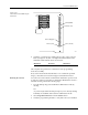
Figure 5-22
Test Points on the MSM 78-pin
Connector
Minimum Nominal Maximum
+14.25V +15.00V +15.75V
178
3940
PIN 28 (8MHz)
PIN 24 (+15V)
PIN 1 (Ground)PIN 78 (+10V)
PIN 72 (Plugged)
2143-1