
User manual


Preventive Maintenance
5-52 ProMaster 2500 User Manual
2. Check the 8 MHz programming electronics clock frequency by
placing the ground probe of your scope (or frequency counter) on
pin 1 (ground) and the input probe on pin 28 (see Figure 5-22).
The clock frequency should read between the minimum and
maximum values shown below:
3. Check the +10V precision reference by reading pin 78 (+10V) using
your digital multimeter (see Figure 5-14). The +10V signal should
read between the minimum and maximum values shown below:
Minimum Nominal Maximum
7.999 MHz 8.000 MHz 8.001 MHz
Minimum Nominal Maximum
+9.090V 10.000V 10.010V
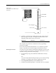
Figure 5-21
Position of the 78-pin Connector on the Mass Storage Module
2142-1
WAVEFORM BOARD
78-PIN CONNECTOR
MASS STORAGE
MODULE