
User manual


Preventive Maintenance
ProMaster 2500 User Manual 5-51
Checking the Reference
Points
The programming electronics (PE) assembly in the ProMaster 2500 has
no service calibration potentiometers that need to be adjusted. The
procedure described below explains how you can confirm the critical
reference levels that must be present for the programming electronics
assembly to run its performance verification and self-test accurately.
If any of the checks described below are outside the specified ranges,
contact Data I/O Customer Support as listed in the Preface.
WARNING:This procedure should be performed only by trained
electronics service personnel. When servicing the
ProMaster 2500, there is significant risk of electric shock
and injury from moving parts (mechanical injury). Do not
attempt this procedure unless you have been trained and
are qualified to do so.
Note: All instruments used for calibrating the ProMaster 2500 must be
maintained under a normal calibration validation cycle.
You will need the following tools and equipment:
• Hex wrench set
• Grounded wrist strap
• Antistatic workstation
• Digital multimeter, accurate to two decimal places
• Oscilloscope or frequency counter
Note: To access the programming electronics, refer to the “Programming
Electronics Assembly Replacement” section in Chapter 7.
Follow the steps below to check the mandatory reference elements used
by the software in the programming electronics assembly during its
performance validation:
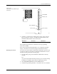
1. Locate the 78-pin connector on the mass storage module (MSM)
board (see Figure 5-21). Pins 1 and 78 are located on the lower end of
the connector; pins 39 and 40 are at the high end, near the RS-232C
connectors on the controller/waveform board.
The pins that you will be checking for this procedure are shown in
Figure 5-21 and are listed below:
•Pin 1: Ground
• Pin 24: +15V input supply voltage
• Pin 28: 8 MHz programming electronics clock
• Pin 78: +10V precision reference voltage