
User manual


Preventive Maintenance
5-38 ProMaster 2500 User Manual
Solenoid Test
Run this test to evaluate the operation of the solenoids.
Note: You can also manually test each solenoid by pressing on the actuator
button on the side of each solenoid.
WARNING:Performing these diagnostic procedures will expose you to
harmful high voltage. Only a service technician trained on
electromechanical equipment should perform the
diagnostic tests described in this manual. If you are not a
service technician who has been trained on the 2500, do
not lift the main plate as described in some of the
diagnostic test procedures.
From the Diagnostics menu, press
2
. The 2500 displays:
When you test a solenoid, confirm that the action it controls is taking
place. If it is not, check the LED mounted directly on the solenoid to see if
it is illuminated. Refer to Figures 5-15 and 5-16 for the location of the
solenoids. An illuminated LED on the solenoid indicates that it is active.
Each solenoid is turned on and off by a control circuit on the handler
controller board.
PRESS NUMBER OF SOLENOID, E TO EXIT
1 - UNUSED 4 - BEAM UP 7 - VACUUM
2 - BLOWER 5 - BLOWER OFF 8 - CLAMP
3 - CUT OFF 6 - HIGH PRESSURE
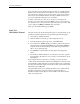
Figure 5-15
Locations of the Solenoids Under the Main Plate
1949-2
SOLENOIDS (2, 3)
MAIN PLATE
(under side)
PROGRAMMING ELECTRONICS ASSEMBLY
SOLENOID (8)