
User manual


Preventive Maintenance
ProMaster 2500 User Manual 5-13
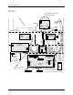
The Controller Board
The components of the controller board are listed below.
•
LEDs
—Used for a quick visual check on the status of various power
supplies, solenoids, and certain logic signals.
•
Connectors
— Route control signals to optics, microswitch, motors,
solenoids, and other components of the handler.
•
Pico fuses
—12 for the stepper motors (two per stepper driver circuit
and four for the traverse motor) and 24 for the dot matrix print head
wires (one fuse for each wire in the print head). Refer to the
schematic in Appendix C for the location of the pico fuses associated
with each motor.
The components of the controller board supply the following:
• Signals to activate the solenoids, the motors, and the labeler wires
• Control signals for the two RS-232C ports and the handler port
• EPROM that contains the handler system firmware
• EEPROM that stores nonvolatile handler parameters
• Circuitry for the optics, the display, and the keyboard
• Microprocessor and kernel logic control
Refer to Appendix C for the controller board schematic and layout.
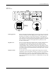
Power Supplies
Four power supply assemblies are located in the body of the 2500. See
Figure 5-4. These supplies operate off the handler’s single AC input.
•
Programming Electronics (PE) Power Supply:
PE
Controller/Waveform board (+15V).
•
Labeler Power Supply
: Print head (+24V)/solenoids
•
Toroid Power Supply
:
• Label advance motor (+36V)
• Input orbital motor (+36V)
• Output orbital motor (+36V)
• Beam head rotation motor (+36V)
• Beam traverse motor (+90V)
•
Controller Board Power Supply:
Logic, vacuum generators, sensor,
optics, RS-232C ports, and the 2500’s display (5V, +/-12V).