
User manual


Preventive Maintenance
5-12 ProMaster 2500 User Manual
High Air Pressure
High pressure air is routed from the high pressure regulator to a Y
connection and is divided into beam high pressure and programming
module clamp assembly air pressure.
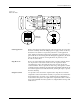
Beam
The beam high pressure air is routed to the beam by a black air line that
passes through the beam and into a straight-in air fitting on the back right
side of the beam. This air passes two milled-in air caps (cavities), which
dampen air spikes, and goes to solenoids
6
and
7
, mounted to the left
center of the beam.
Creating the Beam Vacuum
The beam vacuum required to hold a device on the chuck is created when
solenoid
7
(vacuum) is activated. The high pressure air passes through
the beam passes through the top hole of the vacuum venturi, and escapes
through holes in the bottom of the beam. As this rush of air passes the
venturi, it creates a vacuum at the chuck tip. During the optics test, the
vacuum value should fluctuate between about 26 (when no device is on
the chuck) and 172, with a value of 140 minimum for proper vacuum.
The vacuum is sensed by the vacuum sensor (mounted at the left front of
the beam). When a predefined vacuum level is detected by a device
blocking the chuck tip, the 2500 assumes that the beam has picked up a
device. A malfunction of the vacuum generator, the vacuum sensor, or
the microswitch can cause an error message on the 2500’s display stating
that the beam has dropped the device or is unable to pick up the device.
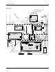
Inserting a Device into the Module
Low pressure air lowers the beam to the programming module contacts.
Additional force is required to insert the device into the programming
module. Insertion begins when the high pressure air present at hole 4 is
switched to hole 5 by beam solenoid 6 (high pressure). This high pressure
passes to hole 21, pushing the ball bearing down and sealing off the low
pressure of hole 19. This allows high pressure to pass to hole 20 and enter
the bottom of the cylinder at hole 18. Air pushing against the fixed piston
pushes the beam down to establish the required continuity between the
devices leads and the module’s contacts.
Programming Module
Clamp Assembly
Programming module clamp assembly air is switched by solenoid
8
to
either open the clamps (to remove a module) or close the clamps (to hold
a module in place). Red air lines carry air to close the clamps; blue air
lines carry air to open the clamps. In-line valves on these lines control the
amount of air entering the air cylinders and allow adjustment so each
side of the clamp opens and closes at the same rate. The in-line valves for
the red lines are in the middle of the air lines, while the valves for the blue
lines are at the base of each air cylinder.