
User manual


Preventive Maintenance
ProMaster 2500 User Manual 5-9
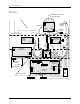
System Air Flow
Air enters the 2500 through a 1/4-inch air connector on the rear and
branches through a Y connection to the low and high air pressure
regulators (see Figure 5-2). The air exits each regulator in two ways: to
the gauge (to display the PSI) and through the 2500 as described below.
Low air pressure should be set to 30 PSI, and high air pressure should be
set to 85 PSI. Solenoids switch high or low air pressure to the beam to
perform various functions, as shown in the table and as described in the
following sections.
Low Air Pressure
Low pressure air is routed from the low pressure regulator to a solenoid
block where it is switched to either the beam or the output track (see
Figure 5-2).
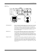
Beam Up/down
This section describes how the air pressure is routed through channels
inside the beam. Refer to Figure 5-16 for the location of the beam
solenoids and Figure 5-3 for the location of air channels as you read this
section.
After the 2500 powers up, solenoid
4
(beam up/down) forces low
pressure air through an air channel in the beam baffle plate from hole 11
to hole 10, up through the beam to hole 16 and hole 17, and finally to the
top of the fixed piston, pushing the beam assembly up into the ready
position. Low pressure air passes through the beam and a single air cap
(cavity), which dampens out air spikes and is routed directly to solenoids
4
and
5
.
High Pressure Low Pressure
Beam vacuum generators Lower beam to pick up device
Lower beam to release device
Final insertion force into
programming module
Initial insertion force into programming
module
Programming module
clamps
Device blow off
Output tube air to start device movement