
User manual


Preventive Maintenance
ProMaster 2500 User Manual 5-7
Optics
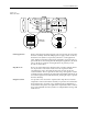
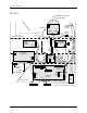
Optics detect and monitor the location of devices, the movement and
position of the beam, labeler movement, orbital motor positions, label
position on the liner (the translucent label backing material), and position
of the ribbon and ribbon pinch roller in the thermal printer (25 and 26 in
Figure 5-1). The optics are mounted in pairs at various places on the
handler. Each pair of optics is made up of an infrared light-emitting
device (emitter) in line with a light-sensitive collector.
All emitters are of two standard types and can be exchanged with like
emitters from any location during troubleshooting. Emitters are
identified by red-and-black or blue-and-black wires crimped to a slide-on
connector. Collectors are identified by blue-and-yellow or red-and-
yellow wires.
Track Optics
The track optics monitor the presence and movement of devices in the
tracks.
Positioning Optics
The reference position optic (17 in Figure 5-1) detects when the beam is at
the far right position and sets the encoder to “0,” which establishes the
starting position of the beam.
Optics 3 and 4 detect the vertical position of the beam.
ADC Label Calibration
Optic
The ADC optic on the dot matrix and thermal label printers senses the
position of labels on the liner so they are positioned properly for the print
head and applied correctly to the device. This optic pair detects the
presence of a label by using the liner as a reference. During label
calibration, light from the emitter passing through the liner is sensed by
the optic collector. As a label on the liner travels between the optic pair,
the decreased light level is detected. When the amount of light increases
again, the ADC optic interprets that change as the end of the label.
Label Sensing Optic
The label-sensing optic on the dot matrix label printer monitors the label
liner and detects when the 2500 runs out of labels.
Switches
A mercury switch on the top cover senses when the hood is open and
causes the 2500 to display a warning message. The 2500 will operate with
the hood up only when you are running the motor diagnostic tests.
A mercury switch on the main plate senses when it is in the raised
position.
A microswitch on the input tube clamp detects the presence of an input
tube (19 in Figure 5-1), and each of the output tube clamps have a
microswitch that detects the presence of an output tube (20 and 21 in
Figure 5-1).
Switches on the front and back side of the programming module engage
when it is properly installed. If the switches do not engage, an error will
be displayed.
Motors
Stepper motors are used on the 2500 to control the movement and
labeling of devices.