
User manual


Preventive Maintenance
5-6 ProMaster 2500 User Manual
If the device programs without errors, the PE goes to a verify cycle. Most
semiconductor manufacturers specify setting the device V
CC
to two
different levels during the device verify cycle, one above and the other
below the nominal operating V
CC
. All fuses in the device are verified at
each level. This tests the device to make certain that the correct data is
read when the device’s V
CC
pin is set slightly below and above the
nominal V
CC
level. The PE sets the device’s V
CC
pin to the specified low
V
CC
level and verifies all the fuses in the device. It then sets V
CC
to the
high level and checks all fuses a second time. If one fuse does not pass
this test when V
CC
is set to the low level, TaskLink displays
VERIFY
FAIL, PASS1
. If the fuse test passes with V
CC
low but fails to verify when
V
CC
is set to its high level, TaskLink displays
VERIFY FAIL, PASS 2
.
When the device passes all these tests, the PE sends a “pass” message to
TaskLink, and the device count in the System Log is advanced. TaskLink
in turn sends a “pass” category signal to the handler. The handler uses
this category status to determine whether to apply a label, and which of
the two output tubes to use.
Device Moves to
Labeler
If the device programmed correctly, and labeling has been selected in the
task, the beam moves the device to the labeler. If the device failed
programming, the beam places the device in the failed device output
track.
Device Is Labeled
The labeler prints a label and the labeler motor advances it between the
platen and the press bearings, into position to be applied to the next
device. The beam pulls the device across the application plate and press
bearings, and the liner wraps around the platen at an angle that allows
the label to peel off. The label is applied to the device as the beam moves
the device forward and past the peeled off label. The label drive motor
and the ADC optic move the next label into position for printing.
Device Moves into
Receiving Tube
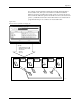
The beam moves the device to the “passed” output track and releases it.
The default designation for the passed output track is output track 1 (see
Figure 5-1). The device release optic detects the device in the track and
the output orbital motor agitates the output orbital assembly, helping the
devices slide into the tube. Devices are also helped into the tube by air
triggered by output track air solenoid 3.
Output tube optics (12 and 14 in Figure 5-1) detect the devices as they
enter the tube. The 2500 counts the devices as they pass between the
output tube optics. When the device count reaches the number set in the
Parts/Tube
parameter in the task, operation stops and the handler
displays
CATEGORY X BIN NOT AVAILABLE
. Operation continues when a
microswitch on the output tube clamp toggles, indicating to the handler
that the full tube was removed and an empty receiving tube has been
inserted.
The following sections describe major 2500 subsystems in greater detail.