
User manual


Preventive Maintenance
5-4 ProMaster 2500 User Manual
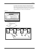
4. A device, positioned against the programming station stop guide,
blocks the beam of the part detect optic. The handler detects the
blocked optic and advances the beam until it is centered over the
device (the location is determined by the pre-defined package size
downloaded by TaskLink). The handler’s firmware stores the
package dimensions for all supported package types. The firmware
prompts the operator to align the first device in a run. The beam’s
traverse motor advances the number of motor steps necessary to
align the chuck over the center of the waiting device.
5. The beam up/down solenoid (solenoid test 4 in Figure 5-16) switches
on the low pressure air to lower the beam. The beam down optic (3 in
Figure 5-1), mounted on the side of the beam, senses the vertical
position of the beam and triggers the high pressure solenoid to
complete the lowering of the beam to the device.
Device Is Inserted into
Programming Module
The rubber chuck tip creates a vacuum seal on the device. When the
vacuum seal has been created, a switch on the left side of the beam is
triggered. The 2500 detects the vacuum and the beam picks up the device.
The beam rises with the device on its tip, moves to the programming
station, pauses so that the operator can align the first device in a run, and
lowers the device into the programming module.
Device Is Programmed
Before the device is programmed, TaskLink and the PE perform several
device tests. Each device-related operation performed by the PE is part of
a programming algorithm specified by the device manufacturer. In most
cases these specifications instruct the PE to perform the following
procedures:
1. A pre-programming check of the device
2. The programming of the device
3. A post-programming data verification cycle
A typical pre-programming sequence includes the following steps:
•
Check for presence of a device in the programming module
—This
verifies that a device is in the programming block.
•
Continuity test
— This confirms that the device pins have continuity
with the module’s contacts. Dirty module contacts or a misaligned
device can cause the handler to fail this test. In case of failure,
TaskLink displays
CONTINUITY TEST FAIL
and records the test result
in the log file.
•
Check for misjustified device
—This confirms that the device
ground and VCC pins match the programming module’s ground and
VCC. (Refer to the device alignment procedure, beginning on page
4-22.) This test also detects devices that have been installed
backwards. When this test fails, TaskLink displays
CONTINUITY TEST
FAIL
.