
User manual


Preventive Maintenance
5-2 ProMaster 2500 User Manual
Theory of Operation
This section describes the operation of each of the ProMaster 2500’s major
components.
TaskLink
You will normally operate the 2500 under the system control of the
TaskLink software program, running on a personal computer (PC).
TaskLink uses a set of computer remote control commands to
communicate with the 2500. These commands control the programming,
handling, labeling, and binning operations of the 2500.
During a typical communication sequence between TaskLink and the
2500, TaskLink issues a command to a subsystem, then yields control to
that subsystem and waits for a reply. The communication sequence will
usually occur in the following manner:
1. TaskLink sends a program command to the Programming Electronics
(PE) subsystem and waits for the PE to complete the procedure.
2. When the PE has completed the procedure, it sends a signal to
TaskLink indicating whether the device has passed or failed.
3. If the device passed, TaskLink looks at the task to determine what
additional procedures need to be performed. TaskLink then sends
the next command to the 2500.
If the device failed, TaskLink displays an error message on your PC
monitor. If the error is related to device testing or programming, the
error code is recorded in a log file on the hard disk of your PC.
Error messages are described in Chapter 6.
4. When a device passes the programming/verify operation, TaskLink
receives a category signal from the programming electronics, and
sends it to the 2500. The 2500 checks the signal against the bin map
and processes the device accordingly.
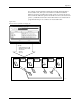
Device Processing
This section describes the flow of a device through the 2500. A device
travels from the input tube to the programming station, then to the
labeling station (if the device passes the verification tests), and then to
one of two output tubes.
Device Moves to
Programming Station
A device travels from the input tube to the programming station in the
following manner:
1. When TaskLink runs a task, it prompts the handler to perform a brief
self-calibration initializing routine before loading the first device.
One of the checks performed during this routine is to see if the hood
is raised. If the hood is raised, the handler displays a warning
message prompting the operator to lower the hood before continuing
the task.
2. The operator inserts a tube containing blank (unprogrammed)
devices into the input tube holder. This action is detected by the
input tube holder microswitches (19 in Figure 5-3).