
User manual


Operation
4-22 ProMaster 2500 User Manual
Calibrating Labels in the
Thermal Printer
The label optic must be calibrated to detect and synchronize with the
labels after you have finished either one of the following operations:
• Installing a new roll of labels
• Changing the ribbon
• Adjusting the ADC reference value
• Manually moving the labels
Perform the following steps to calibrate the labels.
1. Put your finger near the label application point (the right edge of the
application plate).
2. Press
CAL
on the front panel of the 2500.
3. Use your finger to catch the three or four labels ejected while the
labels are being calibrated.
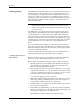
Installing Devices in
the Input Track
The orientation of devices in the input track is critical.
The 2500 uses the
location of pin 1 (as specified in the Task you are running) to determine
how to rotate the beam so that it correctly inserts the device in the
programming module’s block. Because the way you insert devices in the
input track is already defined as part of the Task, you must know your
company’s standards and be careful to insert each tube of devices to
match that standard.
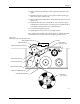
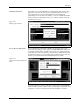
In most cases, the default orientation defined by TaskLink is used. At the
start of a Task, TaskLink displays a drawing with the position that the
Task has defined for pin 1 (see Figure 4-21). Install devices upside-down
so that their leads point toward the ceiling (see Figure 4-17).
The default positions for pin 1 are:
• DIP and SOIC devices: Pin 1 is to the right, closest to the input tube.
• 32-pin PLCC devices: Pin 1 is to the right, closest to the input tube.
• Square PLCC devices: Pin 1 is pointing to the back of the 2500.
CAUTION: Insert all input tubes with the device leads pointing up
toward the ceiling. Insert square PLCC devices with pin 1
oriented toward the back of the 2500, away from you. Insert
rectangular PLCC (32-pin), DIP and SOIC devices so that
pin 1 is oriented to the right. Failure to insert devices so they
match the Task configuration may damage both the device
and the programming module.
To insert a tube according to these defaults, hold the tube so you can see
the top of the devices and the pin 1 indicator (see Figure 4-17). Turn the
tube upside-down (rotate it 180 degrees) and insert the tube in the input
tube holder.