
User manual


Operation
ProMaster 2500 User Manual 4-21
10. Make certain that the label liner is flat against the underside of the
platen.
11. Feed the liner back over the top of the platen and through the gap
between the platen and the track.
12. Thread it between the label drive roller and the label pinch roller (see
Figure 4-16).
13. Thread the liner between it and the drive roller. Guide the spring-
loaded pinch roller back into its operating position against the drive
roller. Make certain that there is no slack in the liner.
14. Lower the label application plate.
15. Lift the labeler cover back into its operating position.
This completes the installation procedure. Be sure to calibrate the labels
as described in the next section before attempting to label devices.
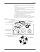
Figure 4-16
Threading Labels in the Thermal Printer
2303-1
LABEL DRIVE ROLLER (hidden)
LABEL PINCH ROLLER
LABEL ADVANCE KNOB
LABEL ALIGNMENT ROLLER
LABEL DETECTION OPTIC
LABEL ROLL
(cover removed)
APPLICATION PLATE (raised)
PLATEN
PRINT HEAD
(retracted position)
LABEL ADC OPTIC
PLATEN PINCH ROLLER