
User manual


Operation
4-20 ProMaster 2500 User Manual
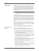
To calibrate labels, do the following:
1. Place your finger next to the press bearings to “catch” the two or
three labels that are advanced during the calibration process.
2. Press
CAL
on the 2500’s keyboard.
3. When the labels stop advancing, calibration is complete.
Loading Labels in the
Thermal Printer
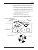
Threading labels on the thermal printer/labeler is similar to threading
labels on the dot matrix printer/labeler (see Figure 4-16). The major
differences on the thermal printer/labeler are:
• The ADC label optic is stationary.
• The retractable rollers (platen pinch and label pinch rollers) snap
back into position if you release them. On the dot matrix labeler, the
rollers remain in the open position.
Note: Do not tighten the label roll on its core. The roll is intentionally loose so
the combination of high temperature and humidity do not cause the labels
to peel incorrectly.
Follow the procedure below to load a new roll of labels into the thermal
printer.
WARNING:A hinged cover protects operators from injury while the
labeler is operating. Be sure that this cover is in place over
the labeler before you start a printing or labeling
operation.
1. Lower the labeler cover.
2. Push the label pinch roller and the platen pinch rollers into their
retracted positions away from the platen.
3. Remove the magnetic cover from the label roll.
4. Install the new label roll on the label supply hub so that the leader
comes off from the right side of the hub (see Figure 4-16).
5. Replace the magnetic cover over the label roll to hold the labels in
place.
6. Prepare the label path by raising the application plate and retracting
the platen pinch and label pinch rollers.
7. Thread about 2 feet (60 cm) of label liner around the left side of the
label alignment roller and through the gap between the application
plate and the output track. Lay the liner along the output track for the
time being.
8. Position the label liner on the underside of the platen and guide the
platen pinch roller back into its operating position against the platen
to hold the liner in place.
9. Thread the liner between the ADC optic and the platen, and then
between the print head and the platen.