
User manual


Operation
4-14 ProMaster 2500 User Manual
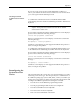
Note: Insert square PLCC devices in the input track with pin 1 oriented toward
the back of the 2500. Insert rectangular PLCC devices (32 pin), DIP and
SOIC devices in the track with pin 1 toward the input tube.
5. Slowly turn the track adjustment knob clockwise to widen the track
until the device just drops into place on the track floor.
CAUTION: Do not close (narrow) the track width while a device is lying
flat in the track; the device leads may be damaged.
Attachment for 8-pin
150-mil SOIC Devices
The 8-pin 150-mil SOIC devices are light enough that they may not rest
flat in the input track while the input orbital assembly vibrates to advance
devices down the track. A device keeper bar assembly attached next to
the input track keeps devices in the proper position in the track. The
keeper bar is oriented parallel to and above the track, allowing 150-mil
SOIC devices to move freely down the track (see Figure 4-11).
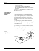
Figure 4-10
Final Track Adjustment
1855-1
STOP GUIDE
DEVICE
OPTIC