
User manual


Operation
4-12 ProMaster 2500 User Manual
Installing a
Programming
Module
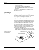
Install the new programming module with the silk-screened
X4
to the
right (toward the input track). Guide pins on the 2500 will not allow you
to install the module backwards. If the beam is centered over the
programming station, insert the module at an angle into position as
shown in Figure 4-8.
The 2500 automatically completes the installation of the module on the
programming pin interface (SPA pins) when you start the Task. System
software controls the release of the module between Tasks and when the
operator requests it by pressing
STOP
(on the 2500’s keyboard) twice.
Pressing
START
closes the clamps on the module again.
Adjusting the Track
Width
Whenever a new Task requires that you change device package type, you
must adjust the track width for the new device. All three track sections
are adjusted by turning the track width adjustment knob (see Figure 4-9).
To adjust the track width, perform the following procedure.
CAUTION: Be sure to adjust the track width according to the following
procedure. Closing the track on a device while it is in the
track may compress the leads and damage the device.
Figure 4-8
Installing a Programming Module
1767-1
FRONT OF 2500
SPA PINS
PROGRAMMING
MODULE
PROGRAMMING STATION
X2
X4
3
X
ALIGNMENT
PIN (1 of 4)
VIEW FROM THE SIDE
FRONT
OF 2500
BEAM
CHUCK
PROGRAMMING
MODULE