
User manual


Operation
4-10 ProMaster 2500 User Manual
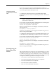
Figure 4-7 shows that the PLCC-28-4 requires two configuration
blocks marked “28A” installed in connectors
X1
and X3 on the
programming module. The two other connectors on the module (X2
and X4) are marked with an asterisk (
*)
to indicate that those
positions should be left open (empty).
3.
Remove the current blocks —
Remove the blocks currently installed
in the module and put them in the correct compartment in the box.
Blocks marked “28A” are located in compartment A.
CAUTION: Be careful when removing the configuration blocks. A
careless removal technique can result in damage to the
configuration connector or to the traces on the board.
4.
Install the new blocks—
Install the blocks in the positions shown on
the box lid’s drawing (see Figure 4-7).
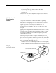
5.
Install the module on the 2500
.
6.
Program devices
.
Figure 4-7
Configuration Box Lid—Optional
Configurations for 28-pin Module.
1670-1
X1
X3
X2 X4
X1
X3
X2 X4
X1
X3
X2 X4
28C
28E
28D 28B
PLCC 28-5
PLCC 28-1 PLCC 28-2 PLCC 28-3 PLCC 28-4
28A 28A
X1
X3
X2 X4
28B 28A
X1
X3
X2 X4
28A
28A
= NO CONFIGURATION BLOCK