
User manual


Operation
ProMaster 2500 User Manual 4-9
Removing Modules or
Moving Configuration
Blocks
This section describes the typical steps involved in checking and
changing the configuration of your module.
1.
Select the device
—On the
Device List
disk, find the device you want
to program in the left-hand columns. The module configuration for
that device is listed in the column labeled “Base.” Sample lines from
the
Device List
disk are shown below:
Part Programmer Package Prod.
Mfr. Number Menu Name Pins Type Footnotes Base Vers.
XXX 22V10-10/-15 22V10-10-PLCC 28 PLCC 3 PLCC-28-2 1.1
XXX CE26V12H CE26V12H-PL 28 PLCC 53 PLCC-28-4 1.1
Most devices are programmed with the “-2” programming module
configuration because it supports standard power and ground pin
locations. For this sample procedure, the selected device requires
“PLCC-28-4” for the programming module configuration. This
means that the device is in a PLCC package, has 28 pins, and must be
configured as a “-4.”
Note: Modules are shipped from the factory without any configuration blocks
installed (the “-1” configuration). Check the ProMaster 2500 Device List
disk for the specific configuration required for the devices you will be
programming.
2.
Select the blocks—
In our example, we open the 28-pin
Programming Module Configuration box. This box has all the blocks
required to make any 28-pin configuration shown on the device list.
Each compartment holds one type of block, marked with a letter. See
Figure 4-6.
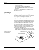
The drawing on the lid of the Module Configuration box shows each
28-pin PLCC configuration, the blocks required, and the positions
where they must be installed on the programming module. See
Figure 4-7. The same information is also shown on the ProMaster
Programming Module Configuration Chart on page 4-10
Figure 4-6
Configuration Box Compartments
A BCD
E
FGH
1680-1