
User manual


Operation
4-8 ProMaster 2500 User Manual
• Is a new label type needed?
• If you changed label type, did you calibrate the labels?
• Have you inserted the input tubes with the correct orientation for
device pin 1?
Descriptions for each of these adjustments are presented in the same
order in the following sections.
Configuring the
Programming
Module
To support the widest variety of devices, the 2500’s programming
modules are jumper configurable so they can support faster, higher
density devices. With higher speed, some devices are more sensitive to
electronic noise levels on signal and programming pins. The
programming modules have configuration blocks that hold the
decoupling capacitors required to take care of possible noise on the
device pins.
To program most devices, you use the module configuration that
supports power and ground pins at their traditional locations. You may
occasionally need to reconfigure the programming module to program
devices that have additional power and ground pins or power and
ground in different locations.
When you reconfigure a module, you place configuration blocks in
locations required by the device. This puts the necessary decoupling
capacitors as close as possible to the device pins where they are needed.
In addition to the programming module, you will need the following
items to complete the configuration process:
•
ProMaster 2500 Device List
disk (shipped with each software update)
• Module configuration box (shipped with each programming module)
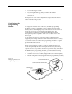
Figure 4-5
Configuring Blocks on a
Programming Module
1649-1
CONFIGURATION BLOCK
CONFIGURATION CONNECTOR
CONTACT SET
(1 of 4)
20A
1X
4X