
Technical data
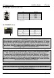


CONTROL PANEL ETV 1961
Page 16 08.07.2014
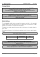
DIAS bus with C-DIAS modules
To ensure a good bus connection, several wiring guidelines must be followed:
It is important to ensure the cables used are designed for the data transfer speed.
Data cables (10, 2 x 2 wire TWISTED PAIR, shielded)
i.e.: LAPPKABEL / UNITRONIC-BUSLEITUNG FD P LD
Due to the internal resistance of the module, the cable impedance should be 100
Ohms.
For twisted-pair cables, caution must be taken to ensure that the correct pair are
connected with one another:
2x2 pair cables: Pair 1 MBUS+, MBUS-
Pair 2 SBUS+, SBUS-
The shielding must be connected to GND over the widest surface and shortest route
possible at both ends
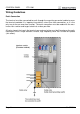
To connect the individual wires to the connector, the insulation must be removed and
the exposed shielding shifted to the side. Only as much insulation as required should
be removed.
It is important to ensure that the send and receive modules are connected to the
same GND potential.
The maximum length allowed for twisted-pair cables 20 M (when using the UNITRONIC
BUS cable FD P LD / Company LAPPKABEL)
La longueur maximale totale d'un câble à paire torsadée est de 20 m (lors de l'utilisation
UNITRONIC BUS FD P LD / Fa. LAPPKABEL).
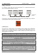
DIAS bus with DIAS modules
The terminal can also be connected to a DIAS module. However, the DIAS modules re-
quire a power supply (a DPS 001, for example) as well as an adapter module for connect
the twisted-pair cable to the ribbon cable connector (i.e.: DKO 012 /013).