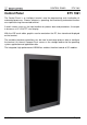
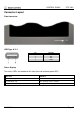
CONTROL PANEL Control Panel ETV 1961 ETV 1961 The Control Panel is an intelligent terminal used for programming and visualization of automated processes. Process diagnosis, operating and monitoring automated function are simplified using the mounted terminal. A touch-screen serves as the input medium for process data and parameters; the output is shown on a 19” VGA TFT color display. With the LSE mask editor, graphics can be created on the PC, then stored and displayed on the terminal.
CONTROL PANEL ETV 1961 Contents Technical Data ............................................................................................ 3 Performance data .................................................................................... 3 Electrical requirements ............................................................................ 4 Terminal ................................................................................................... 4 Control unit .....................................
CONTROL PANEL ETV 1961 Technical Data Performance data Processor AMD Geode LX 800 Cache 128 Kbytes 1st Level 128 Kbytes 2nd Level BIOS SDRAM (SO-DIMM 200-Pin) INSYDE BIOS 256 Mbytes SDRAM (optional up to 512 Mbytes) (There from 16 Mbytes are „Shared Memory“ for the graphic controller) Compact Flash (Type I) SRAM Interface connections 1 Gbyte 512 Kbytes (battery buffered) 1 x CAN-Bus 1 x DIAS-Bus 2 x VARAN-Bus (maximum length: 100 m) 1 x Ethernet 10/100 Mbit 2 x USB V1.
CONTROL PANEL ETV 1961 Electrical requirements Supply voltage Current consumption of the power supply Starting current Maximum +18 V DC Maximum +30 V DC Typically 1.8 A (at +24 V)(without external devices connected) Maximum 20 A for <5 ms The device shall be supplied from an isolating transformer having a secondary listed fuse rated either: a) b) max. 5 amps for voltages 0~20 V (0~28.3 Vp), or 100/Vp for voltages of 20~30 V (28.3~42.4 Vp).
CONTROL PANEL ETV 1961 Display 19” TFT color display Type Resolution SXGA, 1280 x 1024 pixels Color depth 18-Bit (262 x 144 colors) Pixel size 0,294 mm x 0,294 mm Active surface 376,3 mm x 301,1 mm Background lighting 4 cold cathode tubes (CCFT, switchable) Contrast Typically 1300: 1 Brightness Visible field CR>10 von Typically 300 cd/m² Left and right 89°, above and below 89° Miscellaneous Hardware version 1.
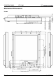
CONTROL PANEL ETV 1961 Mechanical Dimensions in mm Page 6 08.07.
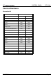
CONTROL PANEL ETV 1961 Chemical Resistance Decorative foil Solution Effect over time 1 hour 24 hours Methyl, ethyl, ketone None None Cyklohexanol None None Acetone None None Ethanol None None Yes Yes 1.1.1.
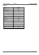
CONTROL PANEL ETV 1961 Touch foil Solution Visual Effect Coal tar oil / toluene None Trichloroethylene None Acetone None Alcohol None Benzene None Machine oil None Ammonia None Glass cleaner None Mayonnaise None Ketchup None Wine None Salad oil None Vinegar None Lip stick None Page 8 08.07.
CONTROL PANEL ETV 1961 Connector Layout Front connector USB Type A V1.1 Pin 1 2 3 4 Function +5V D0D0+ GND Status Display Two status LEDs are located on the front (one red and one green LED). LED status Definition Red and green light simultaneously The ETV 1961 is booting Red LED blinks only The operating system is loading The green LED blinks only The application is running 08.07.
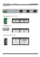
CONTROL PANEL ETV 1961 Rear connectors X1: power plug (FK-MCP 1,5/4-ST-3,5) Pin 1 Pin 1 2 3 4 Function +24 V supply +24 V supply GND GND Pin 1 2 3 4 Function +5 V D0D0+ GND X2: USB Type A V1.1 X3: CAN (Weidmüller B2L 3,5/8) 1 2 Pin 1 2 3 4 5 6 7 8 Function CAN A (CAN LOW) CAN B (HIGH) CAN A (CAN LOW) CAN B (HIGH) GND +5 V GND +24 V 7 8 Page 10 08.07.
CONTROL PANEL ETV 1961 X4: DIAS-Bus (Weidmüller B2L 3,5/6) 12 Pin 1 2 3 4 5 6 Function MBUS+ MBUSSBUS+ SBUSGND n.c. 56 n.c. = do not use X5: ETHERNET (RJ45) Pin 1 2 3 4-5 6 7-8 Function Tx+ TxRx+ n.c. Rxn.c. 1 Problems can arise if a control is connected to an IP network, which contains modules that are not running with a SIGMATEK operating system. With such devices, Ethernet packets could be sent to the control with such a high frequency (i.e.
CONTROL PANEL ETV 1961 X6, X7: VARAN-Bus (RJ45) 1 Pin 1 2 3 4 5 6 7 8 Function TX/RX+ TX/RXRX/TX+ n.c. n.c. RX/TXn.c. n.c. LEDs Yellow Green Function ACTIVE LINK n.c. = do not use LED Color Description ACTIVE Yellow Lights when data is received over the VARAN bus. LINK Green Lights when the connection between the two PHs is established. More information on the VARAN bus can be found in the VARAN bus specifications! Chip-card reader A chip-card reader can be added as shown below.
CONTROL PANEL ETV 1961 Storage Media It is recommended that only storage media provided by SIGMATEK (CompactFlash cards, microSD cards etc.) be used. The number of read and write actions have a significant influence on the lifespan of the storage media. Il est recommandé d’utiliser uniquement les supports de stockage fournis par SIGMATEK (Cartes CompactFlash, cartes microSD, etc). Le nombre de lectures et d'écritures ont un effet significatif sur la durée de vie du support de stockage.
CONTROL PANEL ETV 1961 Wiring Guidelines Earth Connection The terminal must be connected to earth through the mounting on control cabinet or over the terminal provided. It is important to establish a low-Ohm earth connection, as it is the only way to ensure error-free function. The earth connection must be made with the maximum cross section and largest electrical surface possible. All noise signals that reach the terminal over external wiring must be filtered over the earth connection.
CONTROL PANEL ETV 1961 Shielding For the CAN and DIAS bus wiring, twisted pair shielded wires should be used. The cable shielding must be connected to earth either directly before the terminal over a large surface and with low Ohms using grounding clamps or with a blade terminal. With Ethernet and VARAN bus, CAT5 cable with shielded RJ45 connectors is required. The shielding in the CAT5 cable is connected to earth through the RJ45 connector.
CONTROL PANEL ETV 1961 DIAS bus with C-DIAS modules To ensure a good bus connection, several wiring guidelines must be followed: It is important to ensure the cables used are designed for the data transfer speed. Data cables (10, 2 x 2 wire TWISTED PAIR, shielded) i.e.: LAPPKABEL / UNITRONIC-BUSLEITUNG FD P LD Due to the internal resistance of the module, the cable impedance should be 100 Ohms.
CONTROL PANEL ETV 1961 CAN bus Termination In a CAN bus system, both ends must be terminated. This is required to avoid transfer errors caused through reflections in the line. Device 1 Device 2 e.g. CPU DCP 160 e.g. Terminal ET 081 Device 3 CAN bus termination on the clamp module Device n e.g. Terminal ET 805 DSUB plug with termination circuit CAN bus connection If the terminal is one of the end modules, the termination can be made using a 150-Ohm resistor between CAN A (LOW) and CAN B (HIGH).
CONTROL PANEL ETV 1961 Process Diagram Main voltage on Online with Lasal Software? no yes Output of a reset of the peripheral modules Output of a reset of the peripheral modules Deletion of specific data areas Deletion of specific data areas Status RESET Program in external memory module functional? no yes Copy program into application program memory Program in internal memory module functional? Status RUN ROM Copy program into application program memory Call of application program Status R
CONTROL PANEL ETV 1961 Status and Error Messages Status and error messages are shown in the status test of the Lasal Class software. If the CPU has a status display, the status or error number is also show here as well. POINTER or CHKSUM messages are also shown on the terminal screen. Number Message Definition Cause/solution 00 RUN RAM The user program is currently running in RAM. 01 RUN ROM The display is not affected.
CONTROL PANEL 05 WATCHDOG ETV 1961 The program was interrupted through the watchdog logic. Possible Causes: - Interrupts blocked by the user program for an extensive period of time (STI instruction forgotten). - Programming error in a hardware interrupt. - INB, OUTB, INW, OUTW instructions used incorrectly. - The processor is defect. Solution: - Correct programming error. - Exchange CPU. 06 GENERAL ERROR General error 07 PROM DEFECT An error has occurred while programming the memory module.
CONTROL PANEL 15 STOP BRKPT The CPU was stopped by a breakpoint in the program. 16 CPU STOP The CPU stopped by the PG software (F6 HALT in status test). 17 INT ERROR The CPU has triggered a false interrupt and stopped the user program or has encountered an unknown instruction while running the program. ETV 1961 Cause: - A nonexistent operating system was used. - Stack error (uneven number of PUSH and POP instructions). - The user program was interrupted by a software error.
CONTROL PANEL 25 ETV 1961 DIAS ERROR While accessing a DIAS module, an error has occurred. Possible Causes: - An attempt is made to access a nonexistent DIAS module. - DIAS bus error. Solution: - Check the DIAS bus - Check the termination resistors. 26 WAIT The CPU is busy. 27 OP PROG The operating system is currently being reprogrammed. 28 OP INSTALLED The operating system has been reinstalled. 29 OS TOO LONG The operating system cannot be loaded; too little memory.
CONTROL PANEL ETV 1961 45 VARAN ERROR A required VARAN client was disconnected or communication error has occurred. 46 APPL-LOAD-ERROR An error has occurred loading the application. 47 APPL-SAVE-ERROR An error has occurred while attempting to save the application. 50 ACCESS-EXCEPTIONERROR A read or write access of a restricted memory area. (I.e. writing to the NULL pointer).
CONTROL PANEL 70 ETV 1961 C-DIAS ERROR An error occurred in connection with a C-DIAS module. Cause: - The reason for this error is documented in the log file Solution: - Depends on the cause 72 S-DIAS ERROR A connection error with a S-DIAS module has occurred. Possible causes: - real network does not match the project - S-DIAS client is defective Solution: - analyze logfile 95 USER DEFINED 0 User-definable code. 96 USER DEFINED 1 User-definable code. 97 USER DEFINED 2 User-definable code.
CONTROL PANEL 110 C_WRONG_CONNECT No connection to the required channels. 111 C_WRONG_ATTR Wrong server attribute. 112 C_SYNTAX_ERROR Non-specific error. Recompile and download all project sections. 113 C_NO_FILE_OPEN An attempt was made to open an unknown table. 114 C_OUTOF_NEAR Memory allocation error 115 C_OUT OF_FAR Memory allocation error 116 C_INCOMAPTIBLE An object with the same name already exists but has a different class.
CONTROL PANEL 255 ETV 1961 CONNECTION BREAK Further addressing information can be found in the VARAN bus specifications. Page 26 08.07.
CONTROL PANEL ETV 1961 VARAN Recommended Shielding The VARAN real-time Ethernet bus system offers robust performance in harsh industrial environments. Through the use of IEEE 802.3 standard Ethernet physics, the potential between an Ethernet line and sending/receiving components is kept separate. The VARAN Manager resends messages to a bus participant immediately when an error occurs. It is principally recommended that the shielding guidelines below be followed.
CONTROL PANEL ETV 1961 1. Wiring from the Control Cabinet to an External VARAN Component If the Ethernet lines are connected from a VARAN component to a VARAN node outside the control cabinet, the shielding should be placed at the entry point to the control cabinet housing. All noise can then be deflected from the electronic components before reaching the module. Page 28 08.07.
CONTROL PANEL ETV 1961 2. Wiring Outside of the Control Cabinet If a VARAN bus cable must be placed outside of the control cabinet only, no additional shield connection is required. This requires that only IP67 modules and connectors be used. These components are very robust and noise resistant. The shielding for all sockets in IP67 modules are internally connected to common bus or electrically connected to the housing, whereby the deflection of voltage spikes does not flow through the electronics. 08.
CONTROL PANEL ETV 1961 3. Shielding for Wiring Within the Control Cabinet Sources of strong electromagnetic noise located within the control cabinet (drives, Transformers, etc.) can induce interference in a VARAN bus line. Spike voltages are deflected over the metallic housing of a RJ45 connector.
CONTROL PANEL ETV 1961 4. Connecting Noise-Generating Components With the connection of power components that generate strong electromagnetic noise, it is also critical to ensure correct shielding. The shielding should be placed before a power component (or a group thereof). 08.07.
CONTROL PANEL ETV 1961 5. Shielding Between Two Control Cabinets If two control cabinets must be connected over a VARAN bus, it is recommended that the shielding be located at the entry points to both cabinets. Noise can thereby be kept from reaching the electronics within the control cabinet. Page 32 08.07.
CONTROL PANEL ETV 1961 Cleaning the Touch Screen CAUTION! Before cleaning the touch screen, the terminal must first be turned off to avoid unintentionally triggering commands or functions! ATTENTION! Avant de nettoyer l'écran tactile, le terminal doit d'abord être éteint afin d’éviter un déclanchement involontaire des commandes! The terminal's touch screen can only be cleaned with a soft, damp cloth.