
User's Guide
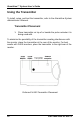
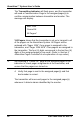
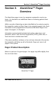
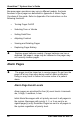
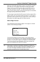
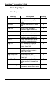
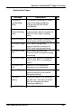
Table Of Contents
- _
- Using this Guide
- Procedures
- Warnings
- Cautions
- Notes
- For More Information
- Safety Information
- System Warnings
- Section 1: AlarmView™ System Overview
- Introduction
- AlarmView™ Transmitter
- AlarmView™ Pager
- AlarmView™ Programmer
- Section 2: AlarmView™ Transmitter Overview
- Transmitter Product Description
- Top Panel
- Antenna Connector
- On/Off Button
- Front Panel
- AC Indicator
- Transmitting Indicator
- Communications Indicator
- Infrared Port
- Rear Panel
- Monitor Input Port
- Power Input Port
- Using the Transmitter
- Transmitter Placement
- Turning Transmitter On
- Turning Transmitter Off
- Operating Transmitter On Battery Power
- Testing System Setup
- Send Test Page
- Section 3: AlarmView™ Pager Overview
- Pager Product Description
- Alarm Pages
- Alarm Page Event Levels
- Alarm Page Format
- Alarm Page Types
- Alarm Pages
- System Error Pages
- Section 4: AlarmView™ Programmer Overview
- Programmer Product Description
- Using the Programmer
- Viewing and Editing Bed Numbers
- Viewing and Editing Pager Numbers
- Viewing and Changing Bed and Pager Assignments
- Viewing Current Transmitter Assignments
- Changing Transmitter Assignments
- Assigning All Pagers from the Transmitter
- Setting Reminder Page Delay
- Section 5: Maintenance, Service, and Support
- Cleaning Procedures
- Inspection and Testing
- Electromagnetic Interference (EMI)
- Appendix A: Basic Pager Functions
- Pager On/Off
- Power On
- Power Off
- Setting the Pager Functions
- Setting Tone
- Setting Time
- Setting Date
- Adjusting Screen Contrast
- Message Mode
- Viewing Messages
- Deleting Messages
- Deleting a Single Message
- Delete All Messages at Once
- Replacing Battery
- Removing and installing the battery
- Appendix B: Basic Programmer Functions
- Safety Information
- General Precautions
- Damage Requiring Service
- Servicing
- Heat
- Water and Moisture
- Accessibility
- Internal Battery
- Rechargeable Battery Pack
- Programmer Functions
- Programmer On/Off
- Turn on Backlight
- Adjusting Screen Contrast
- Setting Date/Time
- Batteries
- Recharging Main Programmer Battery
- Replacing Programmer Backup Battery

16 Part #880-0325-01 Rev. A
AlarmView™ System User’s Guide
The Transmitting Indicator will flash green, and the transmitter
will send a Communication Page to the assigned pager(s) to
confirm communication between transmitter and monitor. The
message will display:
Bed: 1234
Comm OK
All Pagers*
*All Pagers shows that the transmitter is set up to transmit to all
of the pagers on the AlarmView System. All Pagers will be
replaced with “Pager 1234” if one pager is assigned to the
transmitter, and “Pager 1234 5678” if two pagers are assigned to
the transmitter. The four (4) digits correspond to the last four (4)
digits of the assigned pager(s) cap code. (Refer to
Section 3:
AlarmView Pager Overview
for an explanation of cap codes.)
! Not receiving a “Comm OK” page at the assigned pagers is an
indication to check pager assignments at the transmitter, and
ensure that the pagers are turned on.
4. Verify that page is sent to the assigned pager(s) and that
bed number is correct.
The transmitter will now send pages to the assigned pager(s)
whenever it detects alarms identified by the monitor.