
User Manual

AlarmView™ System Administrator’s Manual
880-0326-01 REV. A Page 46
3. Do not connect the equipotential terminal on the analyzer to
any metal on the transmitter.
4. Connect the analyzer to accessible bare metal on the
transmitter (e.g. the antenna connector).
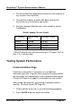
5. Analyzer leakage indication must not exceed the values
listed below.
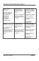
Earth Leakage Current Limits
AC Polarity Neutral Wire
(L2)
Leakage Current
Normal Closed 300 µA
Reversed Closed 300 µA
Reversed* Open 1000 µA
Normal Open 1000 µA
* With AC polarity reversed and neutral wire (L2) open, the line
wire (L1) is actually open.
Testing System Performance
Communications Page
Each time a transmitter is turned on, or re-establishes
communication with a monitor after having lost communication,
the transmitter will automatically send a communications page
(Comm OK Page) to all pager(s) assigned to the transmitter.
After setting up transmitter (connecting it to power and to a
monitor), to send a Comm OK Page test:
1. Check monitor to ensure it is on and functioning properly.
2. Press On/Off button on top of transmitter.