EXHIBIT U – User Manual FCC ID# NMEAVTS1020
Wireless Data Network System User’s Guide The AlarmView™ System is intended for use with Nellcor™ NPB-290, NPB-295, N-395, and N-3000 Pulse Oximeters
AlarmView™ is a trademark of Data Critical Corporation. Nellcor Puritan Bennett Inc. is a wholly owned subsidiary of Mallinckrodt Inc. Nellcor™ is a trademark of Mallinckrodt Inc. Microsoft® and Windows® CE are registered trademarks of Microsoft Corporation. Compaq® and Aero® are registered trademarks of Compaq Computer Corporation. All other trademarks and registered trademarks are the property of their respective owners. © 2000 Data Critical Corporation. All rights reserved.
Table of Contents AlarmView™ Wireless Data Network System User’s Guide Table of Contents Using this Guide .................................................................................... 1 Procedures ....................................................................................... 1 Warnings .......................................................................................... 1 Cautions ........................................................................................... 1 Notes ......
AlarmView™ System User’s Guide Using the Transmitter ..................................................................... 14 Transmitter Placement ........................................................... 14 Turning Transmitter On .......................................................... 15 Turning Transmitter Off .......................................................... 17 Operating Transmitter On Battery Power ........................................ 17 Testing System Setup ..........................
Table of Contents Setting Date ......................................................................... A-4 Adjusting Screen Contrast ................................................... A-4 Message Mode ............................................................................. A-4 Viewing Messages ............................................................... A-4 Deleting Messages .............................................................. A-5 Deleting a Single Message .............................
AlarmView™ System User’s Guide Part #880-0325-01 Rev.
Using This Guide Using this Guide Procedures As you work through this guide, steps to perform are numbered in sequence. For example: 1. Turn monitor off or disconnect cable from transmitter. 2. Press On/Off button on transmitter. Warnings Warnings alert you to potential serious outcomes (including death, injury, or adverse events) to the patient or user. Warnings are identified by this symbol.
AlarmView™ System User’s Guide ! Notes are identified by this symbol. For More Information This guide contains instructions for the daily use of the AlarmView System only. For information on system applications, installation, programming, testing and maintenance, refer to the AlarmView Wireless Data Networking System Administrator’s Manual. 2 Part #880-0325-01 Rev.
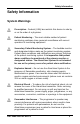
Safety Information Safety Information System Warnings Prescription - Federal (USA) law restricts this device to sale by or on the order of a physician. Patient Monitoring – The most reliable method of patient monitoring combines close personal surveillance with correct operation of monitoring equipment. Secondary Patient Monitoring System – The bedside monitor and designated station make up the patient monitoring system.
AlarmView™ System User’s Guide Radio Frequency (RF) Radiation Safety – The AlarmView transmitter is designed for use as a mobile device as defined by the Federal Communications Commission (FCC). Do not place the transmitter on a patient’s or user’s body. Ensure that the transmitter is located at least 20 cm (8 inches) from a patient or user’s body. Location of the transmitter closer than 20 cm (8 inches) to a person’s body will void the user’s FCC authority to operate the equipment.
Safety Information Transmission Bands – Each institution is responsible for continued surveillance of transmission bands in the facility to prevent co-occupation of bands and cross-band interference. Environment – Data Critical does not assume responsibility for damage caused to the equipment by improper use or installation. Home Use – The AlarmView System is not intended for home use. IEC Standards – When connecting the AlarmView transmitter to any monitor, verify proper operation before clinical use.
AlarmView™ System User’s Guide Section 1: AlarmView™ System Overview Introduction The AlarmView System is a complete, secondary patient monitoring system. AlarmView notifies caregivers of patient events using a wireless network that supplements the primary notification system. AlarmView is intended for use in hospitals and hospital-type facilities, and is installed in care units where pulse oximetry monitors are used.
Section 1: AlarmView™ System Overview more text pagers worn by caregivers. AlarmView™ Pager The pager is worn by the caregiver responsible for the patient. It receives Alarm Pages in the form of text messages from the transmitter, and displays immediate information about the patient and type of alarm. If an alarm condition continues or is not silenced at the monitor, a Reminder Page is sent to all pagers on the AlarmView System.
AlarmView™ System User’s Guide programmer. All transmitters and pagers within one system operate on the same radio frequency and the same baud rate. u The AlarmView pager coverage is limited and designed to cover a care unit only. Operating range from the AlarmView transmitter to pager is approximately 150 feet with no intervening structures (walls, columns, doors, floors, etc.). Coverage is not long range.
Section 2: AlarmViewTM Transmitter Overview Section 2: AlarmView™ Transmitter Overview As with all medical equipment, carefully route patient cabling to reduce the possibility of patient entanglement or strangulation. Do not use an AlarmView transmitter, pager, or programmer that appears to be damaged. The AlarmView wireless data network system is a secondary alarm notification system.
AlarmView™ System User’s Guide alarm from the monitor, then transmits that alarm to an assigned pager or pagers. The alarm is transmitted as a text message to the pager(s). Data relayed includes patient bed number, alarm type, and parameter values. Transmitter Product Description Top Panel Transmitter Top View Antenna Connector Connector for the transmitter antenna. u The antenna must be connected to the transmitter before the transmitter is turned on.
Section 2: AlarmViewTM Transmitter Overview The AlarmView transmitter is designed for use as a mobile device as defined by the Federal Communications Commission (FCC). Do not place the transmitter on a patient’s or user’s body. Ensure that the transmitter is located at least 20 cm (8 inches) from a patient or user’s body. Location of the transmitter closer than 20 cm (8 inches) to a person’s body will void the user’s FCC authority to operate the equipment. On/Off Button Turns the transmitter on and off.
AlarmView™ System User’s Guide u A green AC indicator does not mean that the transmitter is turned on, only that it is connected to power. The Communications Indicator must also be green or amber to show that the transmitter is turned on. Transmitting Indicator Off Transmitter is not attempting to transmit. Amber Transmitter is attempting to transmit, but cannot due to interference (for example another transmitter is transmitting at the same frequency and in the same vicinity).
Section 2: AlarmViewTM Transmitter Overview Infrared Port Allows communication between the transmitter and the programmer. Rear Panel Transmitter Rear View Monitor Input Port Data port for interface cable that connects transmitter to monitor. Power Input Port Input connector for DC power supply. Do not connect the AlarmView transmitter to an electrical outlet controlled by a wall switch, because AC power may accidentally be turned off.
AlarmView™ System User’s Guide Using the Transmitter To install, setup, and test the transmitter, refer to the AlarmView System Administrator’s Manual. Transmitter Placement 1. Place transmitter on top of or beside the pulse oximeter it is being used with. To minimize the possibility of the transmitter creating interference with the monitor, place the transmitter at the rear of the monitor. For best results with N-395 monitors, place the transmitter to the right-rear of the monitor.
Section 2: AlarmViewTM Transmitter Overview Turning Transmitter On 1. Check oximetry monitor to ensure it is on and functioning properly, and that alarm settings are appropriate. 2. Check all transmitter connections: a. Antenna is connected to transmitter, b. Transmitter is plugged in and connected to power (AC Indicator should be green), c. Interface cable is connected to transmitter and to monitor. u The antenna must be connected to the transmitter before the transmitter is turned on.
AlarmView™ System User’s Guide The Transmitting Indicator will flash green, and the transmitter will send a Communication Page to the assigned pager(s) to confirm communication between transmitter and monitor. The message will display: Bed: 1234 Comm OK All Pagers* *All Pagers shows that the transmitter is set up to transmit to all of the pagers on the AlarmView System.
Section 2: AlarmViewTM Transmitter Overview Turning Transmitter Off The transmitter can be turned off only when it is not communicating with the monitor. To turn the transmitter off: 1. Turn monitor off or disconnect interface cable from transmitter or monitor. The Communications Indicator will turn amber after a few seconds. 2. Press On/Off button. The Communications Indicator will turn Off.
AlarmView™ System User’s Guide • A transmitter has been moved to a different monitor. • You are concerned the system is not operating properly. • Any of the transmitter or pager components appear to be or could be damaged. • Any of the transmitter or pager components have been splashed with liquids (and component has been allowed to dry for 24 hours and checked before returning to service).
Section 3: AlarmViewTM Pager Overview Section 3: AlarmView™ Pager Overview The AlarmView pager is worn by caregivers assigned to monitor patients. It is intended as an additional means of receiving patient alarm information. Within seconds of detecting an alarm identified by the oximetry monitor, the transmitter sends an Alarm Page to its assigned pager(s) only. Each transmitter can be programmed to send the initial Alarm Page to one pager, two pagers, or all pagers.
AlarmView™ System User’s Guide Because pager operations may vary in different models, the basic functions of your pager are described in Appendix A: Basic Pager Functions of this guide. Refer to Appendix A for instructions on the following functions: u • Turning Pager On/Off • Selecting Tone or Vibrate • Setting Date/Time • Adjusting Contrast • Viewing and Deleting Pages • Replacing Pager Battery Replace pager batteries weekly.
Section 3: AlarmViewTM Pager Overview When the transmitter generates a page, it is placed in a queue that holds up to four pages while they are being processed. Pages in the queue that have the same priority will be sent in the order they were received. If a higher priority alarm occurs while a lower priority page is being processed by the transmitter, the higher priority alarm will be sent first. If a new page is generated and the queue has four pages with a higher priority, the new page will be discarded.
AlarmView™ System User’s Guide Alarm Page Types Alarm Pages Message 22 Description Priority No Pulse, No Rdg Monitor is not detecting patient motion or patient pulse 3 Asystole Monitor is detecting no heart rate 3 High Sat SPO2% has exceeded monitor’s upper alarm limit 2 Low Sat SPO2% has fallen below the monitor’s lower alarm limit 2 High PR Pulse rate has exceeded monitor’s upper alarm limit 2 Low PR Pulse rate has fallen below monitor’s lower alarm limit 2 High HR ECG measured he
Section 3: AlarmViewTM Pager Overview System Error Pages Message Description Tx Battery Low/Shutting Down Transmitter operating on battery power has depleted battery charge and will shut down immediately Comm Failure/Shutting Down Transmitter has not been able to communicate with the monitor for about an hour and is shutting down Sensor Disconn Sensor has become disconnected from monitor during monitoring ECG/RSP Cable Dis ECG cable has become disconnected from monitor or ECG leads during monitori
AlarmView™ System User’s Guide ! 24 Types of alarms depend on the functions of the monitor. Refer to the monitor’s Operator’s Manual for a more complete listing of alarm types. Part #880-0325-01 Rev.
Section 4: AlarmViewTM Programmer Overview Section 4: AlarmView™ Programmer Overview The AlarmView programmer is a handheld computing device, or personal digital assistant (PDA), that is used to setup and change the configuration of the AlarmView transmitter. Use the programmer to perform the following tasks: • View or edit the list of bed numbers. • View or edit the list of pager numbers and cap codes. • View or change bed number and pager assignments. • Set the Reminder Page Time Delay.
AlarmView™ System User’s Guide Programmer Product Description Below is a picture of a typical programmer. Your programmer may differ slightly from the one shown here. AlarmView™ Programmer Because programmer operations may vary in different models, the basic functions of your programmer are described in Appendix B: Basic Programmer Functions of this guide.
Section 4: AlarmViewTM Programmer Overview u Keep the programmer connected to the AC adapter and plugged in when it is not in use to ensure the programmer is always fully charged. u Ensure that the programmer’s main batteries are charged and a full backup battery is installed at all times or the AlarmView software and hospital specific data may be lost.
AlarmView™ System User’s Guide AlarmView System Manager Main Screen You will also see a ÿ button in the lower left corner of the screen. The Start button is used for installing and configuring the AlarmView System only; you should not need it for daily use of the programmer. A Keyboard button is in the middle of the screen. The keyboard should be visible automatically when it is needed for programming. However, if it is not visible, tap the Keyboard button to open it.
Section 4: AlarmViewTM Programmer Overview 2. A warning screen appears, asking if you’re sure you wish to continue. Tap YES to view bed numbers. 3. The current list of beds 1-24 is displayed. To display beds 25-48, tap Beds 25-48 tab. 4. a. To edit bed number, double-tap or drag stylus across bed number to highlight it, and tap the keyboard characters to enter desired bed number (maximum of six characters). Part #880-0325-01 Rev.
AlarmView™ System User’s Guide b. To delete a bed number, highlight bed number and tap the Backspace key c. until bed number field is empty. To add a cap code (up to a total of 12), tap in an empty cap code field and use the keyboard to enter the new code. 5. If you make an error, tap the Backspace key on the keyboard to delete single characters, or tap RESTORE to restore all values to what they were before you began editing. 6. Tap SAVE to save your changes.
Section 4: AlarmViewTM Programmer Overview Viewing and Editing Pager Numbers Pagers are identified in the system using a Cap Code. Cap codes are 7-digit numbers unique to each pager. The seven (7) digits correspond to the last seven digits of the pager’s serial number (located on the back of the pager). If the serial number is less than seven digits, then add zeros in front. For example, if a pager’s serial number is 45678, its cap code is 0045678.
AlarmView™ System User’s Guide 4. a. To edit pager cap codes, double-tap or drag the stylus across a cap code to highlight it, and then tap on the keyboard characters to enter the desired cap code (must be seven (7) characters). b. To delete a cap code, highlight the cap code and tap the Backspace key until the cap code field is empty. c. To add a cap code (up to a total of 12), tap in an empty cap code field and use the keyboard to enter a new code. 5.
Section 4: AlarmViewTM Programmer Overview ! ! When you save edits to cap codes, entries are automatically resorted in numeric order. The cap codes you changed or entered will move in the display to appear in their new place in the sort, not necessarily in the field where you made the changes. To view an edit you’ve made, look for the cap code in its correct place in the numeric sort. Lists of all cap codes in the AlarmView System are retained permanently in the programmer.
AlarmView™ System User’s Guide Viewing Current Transmitter Assignments To view and change the bed number and pager cap codes assigned to a transmitter, first retrieve the current assignments from the transmitter. Use the following procedure to get current transmitter assignments: 1. Turn transmitter on. 2. Turn programmer on. 3. From SysMgr Main Screen, tap the Assignments button . The programmer will display the assignment screen.
Section 4: AlarmViewTM Programmer Overview 4. Aim the infrared port on the programmer directly at the infrared port on the front of the transmitter and tap the CHECK button. Aligning the Infrared Ports ! The programmer must be within four feet (1.2 meters) of the transmitter and the infrared ports must be aimed directly at each other. Part #880-0325-01 Rev.
AlarmView™ System User’s Guide 5. If the following error message is displayed, tap OK. Check to ensure the transmitter is turned on, check the orientation and the distance, then try again. 6. When retrieval of information from transmitter is successful, the Info Line will change to read “Current Unit Assignment.” The currently assigned bed number will be displayed in the bed number field, and the currently assigned pager numbers will be checked.
Section 4: AlarmViewTM Programmer Overview Changing Transmitter Assignments ! The bed numbers and pagers may be selected and the transmitter programmed without first retrieving the transmitter set up. After you have retrieved the current transmitter assignments into the programmer, use the following procedure to change the bed number and cap code(s) assigned to the transmitter: Part #880-0325-01 Rev.
AlarmView™ System User’s Guide 1. To change bed number, tap the Down Arrow in the bed number field. A current list of all bed numbers will be displayed. Continue to tap the Down Arrow until the bed number you want is displayed. 2. Tap a new bed number from the list to assign it to this transmitter. 3. To change pager numbers, tap the circles to the left of the cap codes to select or deselect pager(s) to assign to this transmitter.
Section 4: AlarmViewTM Programmer Overview 5. Ensure that transmitter is on and pagers assigned to this transmitter are on. 6. Aim the infrared port on the programmer directly at the infrared port on the front of the transmitter and tap the SEND button. ! The programmer must be within four (4) feet (1.2 meters) of the transmitter and the infrared ports must be aimed directly at each other.
AlarmView™ System User’s Guide 7. The Info Line will display “Programming Successful” when transmission is complete. The transmitter will send a Confirmation Page to the assigned pager(s) similar to the following example. Bed: 1234 Programming OK u If a Confirmation Page is not sent to the assigned pager(s), the programming was not completed successfully. Repeat the procedure and check for confirmation. 40 Part #880-0325-01 Rev.
Section 4: AlarmViewTM Programmer Overview ! If the following error message is displayed on the programmer, the programmer’s port could not be accessed. Use the stylus to tap the reset button on the back of the programmer. This will return you to the SysMgr Main Screen. Try the procedure again. Refer to Appendix B for more information. Assigning All Pagers from the Transmitter The All Pagers option can also be selected from the transmitter without using the programmer.
AlarmView™ System User’s Guide 3. Press and hold the transmitter On/Off button until a “Programming OK” confirmation message is received at the pager (approximately 5 seconds). Bed: 1234 Programming OK All Pagers Setting Reminder Page Delay If an alarm condition continues or has not been silenced at the monitor, the transmitter will follow up with a Reminder Page sent once to all pagers in the system.
Section 4: AlarmViewTM Programmer Overview 1. Turn transmitter and programmer on. 2. From SysMgr Main Screen, tap the Service button . 3. The Info Line will read “Press CHECK Button.” Aim the programmer’s infrared port directly at the infrared port on the front of the transmitter and tap CHECK to retrieve the current Reminder Page setting from the transmitter.
AlarmView™ System User’s Guide 4. Tap the Down Arrow in Reminder Page field. A list of delay intervals will display with 30 sec, 45 sec, 1 min, and 2 min intervals. Tap the time delay value you want to store in transmitter. 5. Now you need to program the changed value into the transmitter. Aim the infrared port on the programmer directly at the infrared port on the front of the transmitter and tap the SEND button. 44 Part #880-0325-01 Rev.
Section 4: AlarmViewTM Programmer Overview Transmission is complete when the Info Line reads “Programming Successful” and the pager receives a “Programming OK” page. 6. Repeat step 5 for all transmitters in the system. 7. Tap the Exit button to return to SysMgr Main Screen. Part #880-0325-01 Rev.
AlarmView™ System User’s Guide 46 Part #880-0325-01 Rev.
Section 5: AlarmViewTM Maintenance, Service and Support Section 5: Maintenance, Service, and Support Cleaning Procedures When necessary, clean only the outer casing of the transmitter with a soft cloth, damp with a nonabrasive, commercial cleaner or 70% alcohol solution in water. Lightly wipe surfaces of the transmitter. Use a clean cloth designed for lenses to clean the pager and programmer screens. Use a damp cloth to dust their casings, and wipe dry immediately.
AlarmView™ System User’s Guide Electromagnetic Interference (EMI) The AlarmView transmitter has been tested and found to comply with the limits for medical devices to the FDA guidance for electromagnetic compatibility (EMC). These limits are designed to provide reasonable protection against harmful interference in a typical medical installation.
Section 5: AlarmViewTM Maintenance, Service and Support 1. Turn equipment in vicinity off and on to isolate disruptive equipment. 2. Relocate or re-orient interfering equipment. 3. Increase distance between interfering equipment and this equipment. 4. Manage use of frequencies close to AlarmView System frequencies. 5. Remove devices that are highly susceptible to EMI. 6. Lower power from internal sources within facility control (such as paging systems). 7.
AlarmView™ System User’s Guide 50 Part #880-0325-01 Rev.
Appendix A: Basic Pager Functions Appendix A: Basic Pager Functions The following instructions are for the PerComm model PA8002 pager only. If you have a different pager, contact your administrative personnel or Data Critical for instructions. Not all pager functions will be described here, only the basic functions needed for AlarmView System operations. ! Pressing the left button multiple times will eventually take you back to the pager’s main menu. Pager On/Off Power On 1. Press the ON?”.
AlarmView™ System User’s Guide 3. The screen will show the Standby Screen in the normal condition. Main Screen Power Off 1. Press the key to reach the Icon Screen: 2. Press the press the key to select the Power Off icon , then key to display “POWER OFF?”. 3. Press the u key again to confirm. The pager must be turned on to receive pages. Do not turn the pager off at any time when being used for alarm notification. Doing so may result in failure to receive notice of a patient alarm.
Appendix A: Basic Pager Functions Setting Tone 1. To set the private alert tone, press Alert/Vibration/Sleep Mode button select. 2. Press or 3. Press or to highlight and press to to highlight the Alert icon . to select. 4. Press the to scroll through alert tone options. Press to confirm. 5. Repeat steps 1 through 4 to set public alert also. u The pager should never be used in Vibration Mode absolutely necessary.
AlarmView™ System User’s Guide Setting Date 1. From the Icon Screen, press to select the Time/Date , and press to activate the date format. Set icon 2. Press once to select the Date Format icon to confirm. 3. Press confirm. or to select the format and press and press to Adjusting Screen Contrast 1. From the Icon Screen, press and press Contrast icon scroll/Contrast screen. 2. Press to select the Auto-scroll/ to activate the Auto- to go to the Contrast 3.
Appendix A: Basic Pager Functions Deleting Messages Deleting a Single Message 1. While reading the message, press 2. Press icon. once to select the Single Message Delete 3. Press 4. Press . to show “DELETE?” again to confirm. Delete All Messages at Once to enter the message screen. 1. Press 2. Press , then press twice to select the Delete All icon. Messages 3. Press to show “DELETE ALL?” 4. Press again to confirm. Part #880-0325-01 Rev.
AlarmView™ System User’s Guide Replacing Battery Typical pager battery life under normal usage is one week. When the battery is low, the user will be alerted by a tone, and the Standby Screen . These alerts will subside only will display the Low Battery icon when a fresh battery has been installed. The pager uses one AA Alkaline battery. A fresh battery must be installed within 5 minutes of alert, or all data and memory could be erased. Removing and installing the battery 1.
Appendix B: Basic Programmer Functions Appendix B: Basic Programmer Functions Safety Information General Precautions Retain the product’s safety and operating instructions for future reference. Follow all operating and usage instructions. Observe all warnings on the product and in the operating instructions.
AlarmView™ System User’s Guide Servicing Except as explained elsewhere in the Compaq documentation, do not service any Compaq product yourself. Opening or removing covers that are marked with the symbol to the left may expose you to electric shock. Service needed on components inside these compartments should be done by Data Critical. Heat The product should be placed away from radiators, heat registers, stoves, or other pieces of equipment (including amplifiers) that produce heat.
Appendix B: Basic Programmer Functions Rechargeable Battery Pack Do not crush, puncture, or incinerate the battery pack or short the metal contacts. In addition, do not attempt to open or service the battery pack. Programmer Functions The following instructions are for the Compaq® Aero® programmer model only. If you have a different programmer, contact your administrative personnel or Data Critical for instructions.
AlarmView™ System User’s Guide Programmer On/Off Press and release On/Off button at bottom center of programmer to turn on and off. Turn on Backlight When the programmer is on, press and hold the On/Off button to turn on or off the screen backlight. B-4 Part #880-0325-01 Rev.
Appendix B: Basic Programmer Functions Adjusting Screen Contrast 1. Press the Q button on the left side of programmer. The QLaunch menu will appear on screen. 2. Tap Contrast, then Set Contrast. 3. Tap to increase or decrease contrast and tap OK in upper right corner to return to the main screen. Setting Date/Time 1. Tap Start button. 2. Tap Settings. 3. Tap System. 4. a. To change the time, tap Clock. b. To change the date, tap Date. 5.
AlarmView™ System User’s Guide To check current battery power: 1. Press the Q button. 2. Tap Power. 3. Tap OK to return to main screen. The programmer also has a coin cell backup battery used to preserve data and programming when main batteries have been drained or removed from programmer. u Store the programmer connected to the AC power jack when not in use to ensure that the main battery pack stays charged.
Appendix B: Basic Programmer Functions Charge the battery for at least three (3) hours if the battery is not charged. Replacing Programmer Backup Battery u To prevent the loss of data or programming, ensure that a fullycharged main battery pack is in the programmer before removing the backup battery. 1. Turn off the programmer. 2. Press the recessed button on the back lower left corner of the programmer with the stylus. The cover will pop open. 3. Take out the old battery.
Data Critical Corporation 19820 North Creek Parkway, Suite 100 Bothell, WA 98011 1-888-881-1322 www.datacritical.