
Service Manual

AlarmView™ System User’s Guide
{insert part #} Page 20
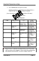
2. Press On/Off button on top of transmitter.
Indicators will flash on and off while transmitter performs a
Power-On Self Test (POST) to check its function.
{Insert transmitter front view with Tx and Mode LED labels}
Transmitter LED Indicators
POST Light Sequence
Stage Stage Indication Test Failure
Indication
1 Tx LED Green Transmitter
program flash
memory check
Simultaneous
flashing of Tx
and Mode LEDs
2 Mode LED
Green
External SRAM Simultaneous
flashing of Tx
and Mode LEDs
3 Tx LED Amber Operation of
IrDA UART
Simultaneous
flashing of Tx
and Mode LEDs
4 Mode LED
Amber
RF board synch
lock
Alternate
flashing of 1 Tx
and 1 Mode
LED
5 Mode LED
Amber
Tx ID flash read Alternate
flashing of 2 Tx
and 2 Mode
LEDs
6 Mode LED
Amber
Setup flash read
Alternate
flashing of 3 Tx
and 3 Mode
LEDs
!
!
!
Stage 6 Failure is indication of hardware failure, even if transmitter
seems to recover (only exception is when installer has programmed
new software into transmitter). In case of a Stage 6 failure, all