
User Manual


PACEMAKER PROCESSING
PatientNet Operator’s Manual, v1.04, 10001001-00X, Draft 101
All information contained herein is subject to the rights and restrictions on the title page.
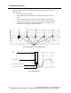
4. You can also inspect the flag and artifacts by recording the waveform on a
strip or a laser printout. You can use manual calipers for the inspection.
Remember the following facts:
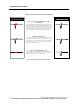
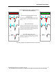
• Not all monitors position the pacer flag in the same place in the data in re-
lation to the actual pacemaker spike or artifact. The flag may be in the cen-
ter of the artifact, or it may precede or follow the artifact. Examine the
location of the artifact and measure it accordingly.
• Widths of the artifacts will vary. Take several measurements and use the
largest interval as the desired “blanking period” setting.
Patients with Impedance-Derived Rate Response Pacemakers
This type of pacemaker emits pulses (20 Hz) for adjusting the pacemaker rate to the
patient’s respiration rate. The front-end device may detect such impedance pulses as
pacemaker spikes and display them in very short, regular intervals, which are super-
imposed on the patient’s ECG waveform. Telectronics manufactures such an imped-
ance-based pacemaker to measure the respiration rate and adjust the pacemaker rate
accordingly.
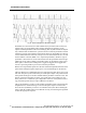
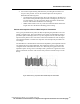
The manufacturer’s documentation states that the impedance pulse amplitude is about
one-tenth of the pacing pulse amplitude. This implies the existence of an electrode
configuration that will enable the transceiver to detect the pacing pulse and not the
impedance pulse. See fig. 46 for an example of the “picket fence” appearance of the
pulses on the ECG waveform. This is more easily noted on real-time strips or in the
history.
Fig. 46. Picket Fencing - Impedance-Derived Rate Response Pacemakers