
User Manual

PACEMAKER PROCESSING
98 PatientNet Operator’s Manual, v1.04, 10001001-00X, Draft
All information contained herein is subject to the rights and restrictions on the title page.
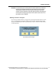
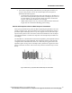
Fig. 42. False Asystole Alarms on Fused Beats
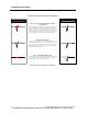
HOW TO VISUALIZE THE EFFECT OF THE
PACER FILTER
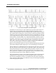
The pacer filter controls how much data is blanked on both sides of a
detected pacemaker spike. The blue flag indicates the position where
the spike was detected. The red line represents the region of pacer
blanking. If there is a fused pacemaker spike on a narrow QRS
complex, the blanking may remove the QRS complex. If false low
rate or asystole alarms are observed, try decreasing the pacer filter.
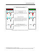
WHAT THE USER SEES
The displayed and printed data show the unfiltered data. There
should be an annotation (N,V,etc.) associated with each detected beat
in the 24 hour data. If missing annotations are noted on fused beats,
decreasing the pacer filter may allow more of the QRS complex
through to the arrhythmia module.
FILTER TOO HIGH FILTER OK
N
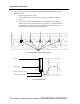
FALSE ASYSTOLE ALARMS ON FUSED BEATS
WHAT THE ARRHYTHMIA SEES
The filtered data is passed to the arrhythmia module. Note that if the
pacer filter is too high some or all of the QRS complex may be
blanked resulting in false asystole or low rate calls.