
User Manual

ARRHYTHMIA ANALYSIS
PatientNet Operator’s Manual, v1.04, 10001001-00X, Draft 55
All information contained herein is subject to the rights and restrictions on the title page.
Step 2 - Data Transmission
The Central Station processes the incoming data and uses digital processing to remove any
artifact from outside sources of RF (Radio Frequency) interference. The digital data stream
received by the Central Station includes the waveform data with encoded pacer flags. The
pacer flags are used to indicate where the front end device (ambulatory transceiver or bedside
monitor) detected a pacemaker spike. The ambulatory transceiver detects the pacemaker pulse
independently in all available leads (I, II, and V for a 5-wire configuration).
Note: Problems with pacemaker detection must be addressed at the front-end
device, the user cannot improve the pacemaker detection performance at
the Central Station.
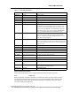
Pacemaker filtering is performed to remove the residual pacer artifact from the ECG data. The
system blanks a specified number of milliseconds before and after pacer flag by repeating the
last ECG sample before the blanking period. The number of milliseconds blanked is deter-
mined by the user configurable pacer filter. The filtered 200 sample per second data is passed
to the QRS detector. See “Pacemaker Processing” on page 95.
Step 3 - QRS Detection
V-FIB Detection
The first step of arrhythmia detection is QRS and V-FIB detection. The QRS detector is a
multi-lead analysis algorithm which detects the presence of QRS complexes or beats. Gross
muscle artifact is detected by using a digital bypass filter and will trigger a MUSCLE call.
Digital signal processing is employed to reject or reduce the effect of muscle artifact, baseline
wander, 50-60 Hz interference, P-waves and T-waves. If no QRS complex is detected for 3-
seconds and less than 12.5% of the samples in the 3-second period are bad (RF dropout), an
ASYSTOLE is called.
Three other alarms may alert the user to a decrease in signal quality or loss of signal: Check
Signal (CHKSIGNAL), Check Lead (CHK LEAD), and No Signal (NO SIGNAL). Check Sig-
nal is triggered when no QRS complex is detected for 3-seconds and more than 12.5% of the
samples in the 3-second period are bad (RF drop out). Check Lead occurs when one or more
ECG leads has a poor connection and/or is causing significant baseline wander. No Signal is
called if there are three consecutive 3-second periods which meet the Check Signal criteria.
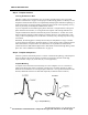
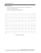
The underlying waveform is analyzed to detect the presence of Ventricular Fibrillation. Ven-
tricular Fibrillation detection is performed parallel to the QRS processing algorithm. Ventricu-
lar Fibrillation is determined by the shape and rate of the rhythm- characteristic of round
rolling low-amplitude waves at a rate of 250-300 per minute. When the monitor sees these
rapid disorganized ventricular impulses with no discernible normal QRSs, the monitor dis-
plays the message V-FIB, initiates a recording and will sound an audible alarm.