
User Manual

ST ANALYSIS
168 PatientNet Operator’s Manual, v1.04, 10001001-00X, Draft
All information contained herein is subject to the rights and restrictions on the title page.
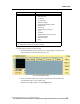
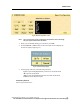
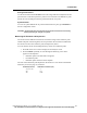
The ST Analysis screen shows current and learned ST templates for up to seven leads,
including derived leads (III, aVR, aVL, aVF) for central arrhythmia source patients.
ST analysis is always performed on augmented leads regardless of whether they are
displayed, so you can review augmented lead ST data at a later time.
An ST template is the current 16 or 32 beat average of the last 16 or 32 normal beats
for the lead. ST templates are updated every time the 16 or 32 beat average is updated.
(See “Selecting an Average Beat for ST Template Generation” on page 172.)
If an elevation or depression violation occurs on a lead, the ST level is shown in flash-
ing red.
Note: The DT-4500 Ambulatory Transceiver supports 3, 4, and 5-wire at this time.
ST Measurement
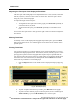
Viewing Current ST Measurements
To view the current isoelectric point and ST start and end points for all available leads:
1. On the ST Analysis screen toggle the ST Points button to display hash marks
at current ST measurement points.
2. Toggle the Grid button to turn gridlines on the templates on or off.
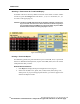
Measuring the ST Segment
You can set or change a patient’s ST measurement points on one of the three leads.
Press ST Config on the Patient Settings screen to display the ST Configuration screen.
(If ST Analysis is disabled for the selected patient, a popup asks if you want to enable
ST Analysis. Choose Yes.)
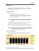
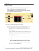
Set individual ST measurement points as shown below.
Isoelectric (ISO) Point
1. To have the system determine the ISO, toggle Auto ISO button to On.
2. To set the ISO yourself, first toggle Auto ISO button to Off and then perform
one of the following:
a. Press the arrow buttons under ISO to change the isoelectric point. ISO val-
ues range from 5 to 250 ms before Q point, in 5 ms increments. The default
is Q point minus 30 ms.
b. Click and drag the white vertical line on the large ST template to the de-
sired location. Notice that the value in ISO window changes as you move
the line.
ST Segment Starting Point
Use the arrow buttons under ST Start or move the green slide bar to set the start point
of the ST segment between 0 and 295 ms past the J point. The default is J point plus 40
ms.